The Pairing of Electric Hoists and Overhead Cranes: Far More Than Just "Hanging It Up"
The integration of an electric hoist with an overhead crane is by no means a simple process of "picking the right capacity and hanging it up." It entails a complete set of matching logic that needs to be figured out in advance.
A Lifting Mechanism, and Much More a Part of the System
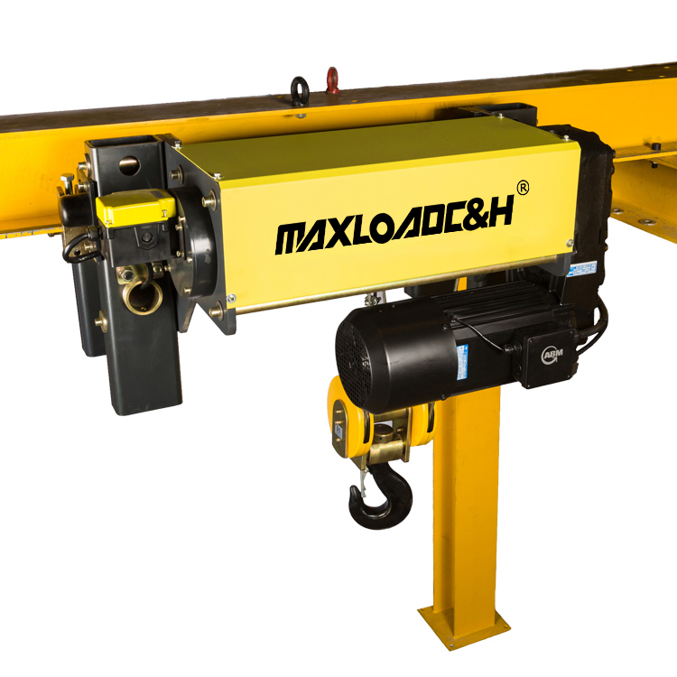
In typical industrial applications, the electric hoist is often viewed as a standalone component. In reality, however, it forms a complete spatial material handling system together with the crane's bridge structure, the bridge travel mechanism, and the power supply system. The most common configuration is the single-girder overhead crane: the crane’s main beam is either a hot-rolled I-beam or a welded box girder. The electric hoist, with its own built-in trolley, travels transversely along the lower flange of the I-beam or on a track laid on the top flange, while the crane’s bridge travels longitudinally along the runway rails on the plant corbels. Together, they cover a rectangular working area. For heavier capacities and higher duty classifications, in double-girder cranes, the electric hoist is often designed as a winch trolley seated on tracks mounted atop the two main girders, creating a two-level travelling structure.
In either configuration, the vertical lifting motion and the cross-travel motion of the hoist combine with the long-travel motion of the crane bridge to realize spatial material handling. The degree of coordination among these three movements directly determines the stability of the lift, the positioning accuracy, and the overall service life of the entire system. Therefore, an electric hoist and an overhead crane are never isolated procurement items; they are a pair that absolutely must be designed jointly as an integrated unit.
The Data Most Easily Overlooked During Selection
When it comes to model selection, most people immediately focus on the lifting capacity, lifting height, and span. Often overlooked, however, is the parameter that truly dictates service life—the duty classification. A 10-ton capacity used in a die-repair workshop for less than two hours a day is subjected to completely different demands compared to the same 10-ton capacity used non-stop over two shifts in a steel processing line. The duty classification of the electric hoist must be coordinated with that of the crane bridge. As a rule, the hoist’s duty classification should not be lower than the overall classification of the crane. If the crane bridge is designed for M5 duty, but a standard hoist rated only for M3 is installed, the hoist’s gearbox and brake will fail frequently in a short time. The cost of subsequent on-site replacement is far greater than upgrading the selection at the beginning.
Load spectrum verification cannot be based solely on experience. A certain production line might have a rated load of only 3 tons, but if every cycle approaches full load and the hourly cycle count exceeds 30, the actual load spectrum condition may already hit the M6 level. In such a case, choosing a hoist based purely on capacity overlooks a host of issues, such as overheating of the lifting motor and burning of contactor tips. Alongside the load spectrum, the cyclic duration factor of the hoist’s lifting motor must match the actual operating conditions; otherwise, the motor’s lifespan will be drastically reduced.
The coordination of travel speeds is another parameter easily glossed over. When the hoist is moving transversely at high speed with a load at the same time that the crane bridge is accelerating or decelerating, the swing amplitude of the load increases significantly. This not only affects positioning accuracy but also imposes additional horizontal inertial forces on the crane's end carriages. If high-speed operation is required, the hoist trolley drive should ideally use variable frequency speed control, and the crane bridge drive should also adopt variable frequency control, with appropriate acceleration and deceleration ramps being set. If variable frequency drives are not available, at the very least, the electrical control system must coordinate the lift brake with the bridge travel logic to prevent a sudden pick-up during a sway event, as that would transmit the full impact load back to the bridge structure.
Countless Reworks Lie Hidden in the Interface Details
From a purely mechanical interface perspective, an experienced technician will first check the matching relationship between the hoist trolley wheel tread and the crane rail. For a single-girder crane using an I-beam as the main beam, the slope of the hoist trolley wheel tread must match the slope of the I-beam’s lower flange. The lower flange slope of domestic hot-rolled I-beams is typically 1:6, whereas some wheels manufactured to different standards have a different tread angle. If these are forcibly mixed, operation might be barely possible initially, but within a month, uneven wear and rail edge friction (skewing) will occur. In severe cases, this can cause localized plastic deformation of the I-beam’s lower flange. Likewise, if a hoist with a rated wheel load that is too high is mounted on an I-beam with insufficient load-bearing capacity, a permanent downward sag of the lower flange surface can form. This not only causes the hoist to seize during travel but also creates a hidden danger of the flange tearing under extreme conditions.
For box girder cranes, slope matching is not an issue, but the gauge deviation, horizontal curvature, and joint height difference of the hoist trolley track are absolutely critical. If the trolley track is not precisely leveled and aligned during installation, once the hoist is under load, typically only three or even two of its four wheels will actually bear the load. This manifests at the hook as random load swinging, easily causes the hoisting wire rope to jump its groove, and subjects the entire crane steel structure to additional torsional stress.
On the electrical interface side, the hoist is typically powered by a festooned flat cable or a towline system, while the crane bridge generally relies on conductor bars. During the design phase, it's essential to simulate whether the cable's bending radius is sufficient when the hoist travels to the extreme ends of the crane bridge and whether it will chafe against the end carriages or the current collector bracket for the conductor bar system. Electrical interlocks are an even more critical safety baseline: when the hoist’s overload limiter activates, it must not only cut off the lifting upward motion but also automatically cut off the power supply for both the bridge travel and the hoist trolley travel, only allowing lowering for unloading. Similarly, the hoist's upper limit switch must be wired in series with the control circuits for both long and cross travel. The absence of these interlock logics might seem like saving wiring effort, but in reality, it exposes operators to enormous safety risks.
Differences Across Application Scenarios Are Far Greater Than Expected
In a typical machining workshop, a 3-ton or 5-ton single-girder crane equipped with a conventional wire rope electric hoist is often sufficient for machine tool loading and unloading tasks. However, in these cases, the lifting speed needs to be chosen carefully. An excessively high lifting speed can very easily cause bumping when handling precision dies. If the budget permits, using a two-speed or variable-frequency lifting drive can achieve a good balance between efficiency and safety.
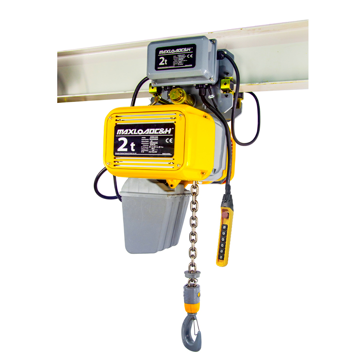
Assembly lines are a typical application for electric chain hoists. Chain hoists offer excellent low-speed stability and precise inching capability. When paired with a light-duty single-girder crane featuring anti-tilt rollers or a modular suspended crane system, they make it very convenient to realize point-to-point assembly between workstations. However, on assembly lines with frequent human-machine interaction, the response delay and emergency stop functions of the hoist's pendant control or remote control must be repeatedly verified, as they directly affect the operator's working rhythm and personal safety.
For workshops with special environmental conditions, such as those in paper making, printing and dyeing, or food processing, the hoist protection class must be at least IP55. The crane’s electrical control cabinets need comprehensive anti-corrosion treatment, and the hoist’s wire rope should preferably be made of stainless steel or have a protective coating. In chemical or painting workshops with potentially explosive gas hazards, a full set of explosion-proof electric hoists and explosion-proof overhead cranes must be used. The crane’s bridge travel mechanism cannot use conventional conductor bars; instead, it must adopt a soft cable with an explosion-proof cable trolley system or pneumatic drive. These configurations cannot be achieved through partial retrofits later on. If these are omitted in the early stages, the loss is the regulatory compliance of the entire equipment.
A Mindset Shift to Avoid Detours
Looking back at field cases accumulated over many years, the workshops whose equipment remains in good condition after more than a decade of operation have, almost without exception, designed the electric hoist and the overhead crane as a single integrated system from the very start. In contrast, projects that are plagued by wheel and brake replacements every few days usually suffer from insufficient upfront calculation—perhaps the wheel load verification was neglected, the duty classification was chosen incorrectly, or the clearance dimension chain was miscalculated by a centimeter or two, causing the hoist to interfere with the end carriage and forcing on-site cutting and modification.
Therefore, when an experienced engineer repeatedly emphasizes that a hoist and crane must be "paired" rather than "thrown together," what lies behind this is a mindset of system integration. For those formulating the solution, it is only by stepping beyond the procurement mindset of buying piecemeal components and synchronously considering five dimensions—load, motion, interfaces, control, and safety—that this most common material handling combination can truly be reliably embedded into the entire production process, maintaining stability through the daily cycle of heavy lifting and lowering.
 0086 156 1824 5535
 0086 156 1824 5535