Key Technical Points from Selection to Installation
In modern industrial material handling scenarios, overhead cranes perform the function of moving materials across workshops and workstations. The electric hoist, as the core lifting mechanism of the crane, directly determines the load capacity and working efficiency of the entire handling system. The coordinated pairing of the two is not simply a physical attachment of "one hanging from the other"; rather, it is a systematic engineering task involving work duty matching, runway adaptation, electrical coordination, and control logic.
I. The Underlying Logic of Pairing: Coordination between Lifting Mechanism and Load-bearing Structure
The essence of any lifting and handling system is a mechanical chain composed of a load-bearing structure, a lifting mechanism, a travelling mechanism, and a control system. Within this chain, the bridge or runway system of the overhead crane provides extensive planar coverage, the electric hoist is responsible for vertical displacement of heavy objects, and the travelling trolley serves as the motion hub connecting the two.
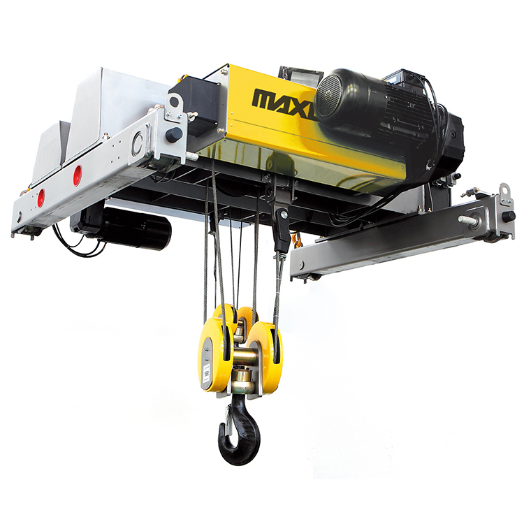
The electric hoist is suspended from the bottom flange of the I-beam runway on the crane main girder by its travelling trolley. The movement of the trolley along the runway and the lifting motion of the hoist superimpose upon each other to form a two-dimensional or three-dimensional working range. It is crucial to understand that the electric hoist does not exist independently on the crane; every lift and descent imposes a reaction force on the crane’s main girder, and every long-travel motion of the crane generates inertial forces on the hoist and the load. Therefore, the pairing scheme must consider the electric hoist and the overhead crane as a unified load-bearing entity.
From the perspective of design standards, GB/T 3811 "Design Rules for Cranes" divides the overall work duty classification of the crane into eight grades, from A1 to A8, while the electric hoist’s lifting mechanism also has corresponding mechanism classification grades from M3 to M8. Ideally, the work duty class of the electric hoist should correspond to that of the crane as a whole, and should at least not be lower than the design requirement of the crane. For example, if a bridge crane with a work duty class of A5 is fitted with an electric hoist whose mechanism classification is only M3, although it may function barely in the short term, the gears, brakes, and wire ropes of the lifting mechanism will be subjected to load spectrums and frequencies higher than their design benchmarks for prolonged periods, causing a drastic reduction in fatigue life. During the selection process, this is an easily overlooked yet far-reaching technical detail.
II. Core Aspects of Load Matching: Lifting Capacity and Cyclic Duration Factor Considerations
Selecting the lifting capacity of an electric hoist seems straightforward, but in actual pairing, three levels must usually be considered: the rated lifting capacity, the actual frequency of use, and the distribution of the load spectrum. According to the national machinery industry standard JB/T 9008.1, the lifting capacity range of wire rope electric hoists covers 0.16 tonnes to 80 tonnes, with the most common configurations in practical crane-hoist pairings being within the 1-tonne to 32-tonne range.
However, these are only static parameters. More critical is the selection of the cyclic duration factor and motor duty type. The drive motor of an electric hoist is typically designed for intermittent periodic duty with S3-40%, meaning that within one working cycle, the energized time proportion does not exceed 40%. If, under actual operating conditions, lifting actions are frequent and load holding times are long while the selected hoist has a low JC value (Cyclic Duration Factor), the motor's heat dissipation time will be insufficient, winding temperatures will continuously rise, insulation aging will accelerate, and the motor will eventually burn out. This type of failure is particularly common in high-temperature, heavy-duty, and high-cycle conditions such as heat treatment workshops and foundries.
Therefore, when pairing an electric hoist, one should not simply select based on the "maximum weight". Instead, the choice should be made according to the actual load spectrum and operating frequency. If necessary, choose a model with a higher work duty classification, or adopt a hoist with dual-speed or variable frequency speed regulation functions to balance the thermal load by reducing speed under certain operating conditions.
III. Installation Structural Points: Trolley Matching and Runway Adaptation
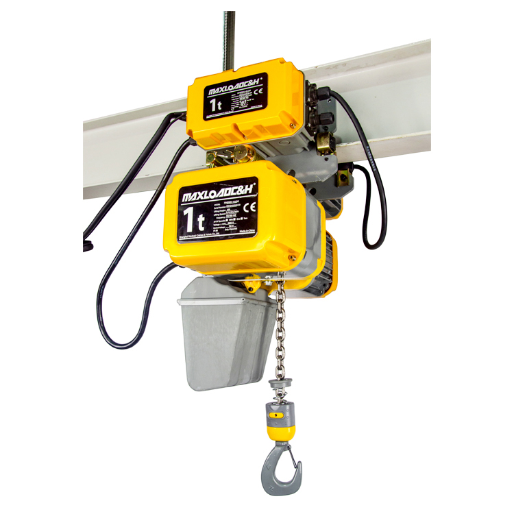
The connection between the electric hoist and the overhead crane main girder is achieved through the travelling trolley. Whether it is a wire rope electric hoist or an electric chain hoist, when installed on an I-beam runway, the principle of one-to-one correspondence between the trolley model and the hoist model must be strictly followed. The direct consequence of a model mismatch is a change in the wheel pressure distribution of the trolley, which can lead to running jamming, eccentric runway wear in minor cases, and derailment or falling accidents in severe cases.
When installed on an I-beam, the spacing between the trolley wheels needs to be precisely adjusted according to the actual width of the runway flange. Taking a common electric trolley installation as an example, the technician first removes the passive wheels on one side, inserts the axles of both sides into the connecting holes of the electric hoist, and ensures that the number of shims on both axles is consistent. Then, the trolley spacing is measured to be approximately 3 to 5 millimetres wider than the flange width of the I-beam, ensuring that the trolley can slide smoothly along the runway without excessive clearance that would cause wobbling. Spacing that is too large or too small directly affects operational smoothness and safety.
For scenarios using electric chain hoists, it is also necessary to pay extra attention to whether there are paint or grease residues on the running surface of the trolley runway. The runway’s working surface should maintain its bare metallic appearance; painted surfaces reduce the friction coefficient between the drive wheel and the runway, leading to slippage and inaccurate positioning.
IV. Common Application Scenarios and Supporting Scheme Selection
The pairing scheme of electric hoists and overhead cranes is highly dependent on the specific application scenario. In general machining workshops, a common pairing is a single-girder bridge crane with a work duty class of A3 to A4 and a capacity under 5 tonnes, matched with a constant-speed electric hoist. The lifting speed is usually 8 m/min and the trolley travelling speed is about 20 m/min. This is sufficient for transferring components between workstations. This scheme features a compact structure and moderate investment cost, and it is the most frequently used pairing form in small and medium-sized manufacturing enterprises.
In automotive welding and body-in-white workshops or assembly lines, higher positioning accuracy is required. In such cases, the overhead crane often adopts a combined suspension structure paired with a low-headroom electric chain hoist. The lifting loads range from a few hundred kilograms to several tonnes, and the lifting and travelling speeds require dual-speed or variable frequency adjustment capability to achieve millimetre-level alignment of workpieces. A typical application is the marriage station for the body-in-white and chassis, where the electric hoist, crane, and tooling fixtures form a semi-automated transfer unit. Operators perform lifting, traversing, and fine-tuning actions via wireless remote control, greatly reducing the intensity of manual intervention.
V. Integration of Electrical Coordination and Control Systems
A professional pairing scheme must also fully consider the compatibility of the electrical systems. The electric hoist and the overhead crane long-travel mechanism usually share a common power supply system, with three-phase 380V AC being the most common configuration. However, it is important to note that significant voltage drops and current surges occur at the moments of starting and braking the electric hoist. If the cross-sectional area of the crane's main power supply line is insufficient or the transformer capacity margin is inadequate, frequent operation of the hoist during long-travel movements of the crane can cause system voltage fluctuations exceeding limits. According to relevant technical specifications, the allowable voltage fluctuation limit for motors and electrical equipment is +10% to -15% of the rated voltage, and the internal voltage loss of the crane should not exceed 3%.
At the control level, the current mainstream solution is to integrate the electric hoist and the crane long-travel into a single wireless remote control system, allowing the operator to control movements in three directions—up/down, left/right, and forward/backward—simultaneously using one transmitter. Although this integration method is convenient, special attention must be paid to the logical interlocking of the control circuits during wiring—when the crane is performing a long-travel motion, the lifting and lowering of the hoist should not be accidentally triggered, and vice versa. Some design schemes also incorporate a real-time load monitoring system, integrating load cells at the hook or wire rope anchorage points. When the load exceeds 90% of the rated capacity, a warning is issued; when it exceeds 100%, the lifting circuit is automatically cut off, further mitigating risks arising from operator misjudgment.
VI. Practical Considerations for Safety and Maintenance
No lifting system should discuss efficiency improvement in isolation from safety management. The pairing scheme of the electric hoist and the overhead crane must reserve sufficient space for routine inspection and maintenance. Wire rope electric hoists should not be left in a suspended state while bearing heavy loads for extended periods—under continuous tension, the wire rope undergoes plastic elongation, the internal strands are gradually stretched and thinned, leading to broken wires in severe cases; internal transmission components such as gears and bearings also experience accelerated wear due to prolonged one-sided force.
During daily use, the operator should check before each operation whether the connecting bolts of the hoist and trolley are loose, whether the clearance between the trolley wheel flanges and the runway flange is normal, and whether the brake response is sensitive. After completing the work, the heavy load must not be left suspended from the hoist hook for a long time. The spreader should be returned to a no-load state, and the main power supply should be cut off. For workshop environments with high dust and high humidity, it is also necessary to regularly clean dust and debris off the runway’s running surface to maintain effective friction between the trolley drive wheels and the runway.
Conclusion
The pairing of an electric hoist and an overhead crane appears to be a fundamental configuration for industrial material handling, but in reality, it involves systematic knowledge spanning mechanical structures, electrical controls, and safety management. A pairing scheme that can stand the test of long-term verification is inseparable from an accurate assessment of work duty classification and load characteristics, rigorous control of installation tolerances and runway adaptation, and the logical integration of electrical and control circuits. Only by mastering these technical points can this lifting combination truly achieve precision, efficiency, stability, and reliability in daily operation.
 0086 156 1824 5535
 0086 156 1824 5535