How to Achieve Efficient Coordination Between Electric Hoists and Overhead Cranes
In industrial workshops, it is extremely common to use electric hoists in conjunction with overhead cranes for material lifting and handling. Yet, with this seemingly simple combination, on-site problems crop up one after another: the hoist trolley flange contacts the rail, causing edge friction, the crane bridge sways severely and cannot achieve precise positioning, and even under heavy load, the hoist suddenly slips or drops the load... When you look closely, most of these issues stem from insufficiently thorough matching between the hoist and the crane. This article does not intend to start from scratch with crane classifications; instead, it will directly cut to the matching logic that is truly useful on site, discussing those details that are easily overlooked but critically important.
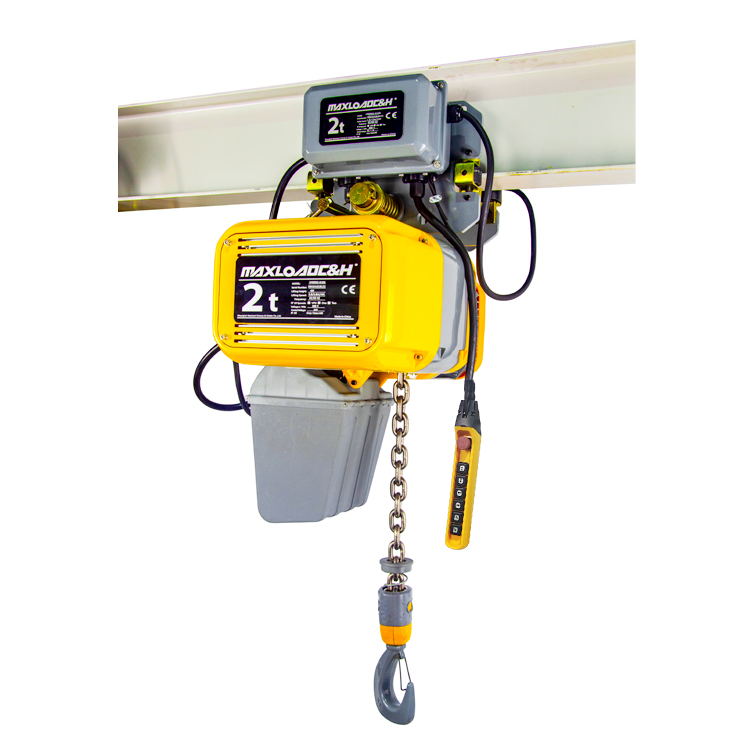
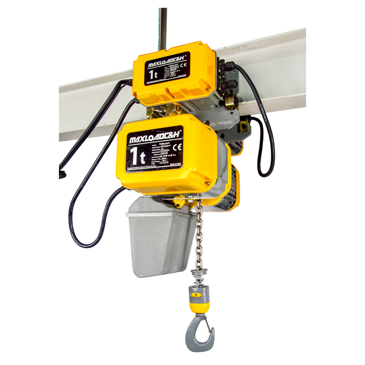
To understand the matching, first see clearly how the hoist is "hung" onto the crane. The most typical single-girder crane usually has a running electric hoist suspended directly under the main beam — the hoist comes with its own running trolley, riding on the lower flange of the main beam. This solution is compact in structure and cost-controllable, commonly used in workshops for capacities up to 20 tons. The contact surface between the wheels and the lower flange appears simple, but in reality, it has strict compatibility requirements: the wheel flange spacing and wheel tread width of the hoist trolley must be compatible with the width and slope of the I-beam lower flange. If the lower flange is too narrow or too wide, the trolley will jam or deviate; if the crane beam's deflection exceeds the standard, the hoist may automatically drift toward the center at mid-span. During installation, this must be compensated for by adjusting the camber of the crane runway rail. Double-girder cranes adopt a different approach. The hoist is usually fixed onto a trolley frame that travels along the two girder rails; the entire hoist can be directly fixed, or the hoist can be allowed an additional level of running on that trolley frame. This yields greater lifting height and headroom, facilitating the lifting of tall workpieces. Regardless of the structure, the bolt strength and shear design at the connection points between the hoist and the crane must not be casually dealt with. The precision of the hole-making directly determines the smoothness of the operation; on-site match-drilling often results in a more suitable fit than purely relying on drilling per the drawing.
In terms of parameter selection, most people first fix their attention on the lifting capacity. But do not forget: the "rated lifting capacity" of the crane includes the weight of the lifting attachment and the hoist's own weight, especially when calculating the wheel loads of the crane and the power supply capacity, which must all be factored in together. A frequently seen situation is: the crane is selected with a capacity just a little greater than the maximum workpiece weight, neglecting the dead weight of the hoist and specialized lifting attachments. As a result, during trial lifts, although the load can be lifted, the crane bridge starts sluggishly, and the sliding distance during braking becomes noticeably longer — this is actually a warning sign that the total load is approaching the limit. Next is the work duty group, a parameter that is often downgraded. A very practical way to judge: directly count the number of lifts per day and the average load rate. For example, in a mold repair workshop where workpieces of about 5 tons are lifted around 50 times a day, with a single lift height of about 6 meters, and where the crane often travels with the load, the hoist in such conditions should be at least M5, and the crane travel mechanism likewise at least M5. If the hoist is downgraded to M4 for cost reasons, the wire rope, drum, and brake will soon show abnormal wear, and the probability of the rope guide breaking will increase significantly. The matching of lifting speed and travel speed also affects the working rhythm. On assembly lines with high positioning requirements, a single-speed hoist often drives people crazy — the load has not yet stabilized from swinging before it must be forcibly lowered, making product damage unavoidable. In such cases, a dual-speed hoist or variable frequency hoist is a wiser choice. Variable frequency control is likewise recommended for the bridge and trolley travel; pre-decelerating to about one-tenth of normal speed before braking can keep the load swing amplitude within a very small range, making manual alignment much easier.
Coordination on the electrical and control side is another pitfall-prone area. Quite a few workshops operate the hoist and the crane with two separate remote controls. It seems non-interfering, but when the operator is in a hurry, pressing the hoist up and the crane fast traverse at the same time, the load may whiz past equipment, dramatically increasing the danger. A safer approach is to carry out necessary interlocking through an integrated control system: for example, setting that the crane's fast traverse is only allowed after the hoist hook has risen above a certain height, higher than the tallest obstacle on the path; or limiting the hoist lifting action when the bridge and trolley are both running at high speed to avoid dynamic impact. Limit protection must be considered in series. The hoist’s upper and lower limit switches only control the hook travel and cannot manage the crane's end-of-travel limits. Separate limit switches and buffers must be set at the two ends of the crane runway rails, and the limit stops for the hoist trolley travel must be accurately placed at the end of the trolley stroke. For power supply, the hoist typically uses a festoon cable trolley system, and the crane bridge uses a safety conductor bar. Voltage drop must be calculated. There have been on-site lessons learned where excessively long feeder lines caused low voltage, leading to delayed release of the hoist brake and motor burnout due to overheating. Therefore, the cross-section and length of the incoming line must be determined based on the maximum starting current of the hoist.
The focus of the matching varies significantly under different scenarios. In a machining workshop, where workpiece clamping is key, the hoist's inching positioning accuracy is highly valued. For this purpose, a mechanical micro-speed or variable-frequency zero-speed load holding function can even be added to the hoist's lifting mechanism, and the crane bridge also needs slow jogging to ensure that heavy spindles and gearboxes are set in place without damaging the locating pins. Assembly lines pursue a balance between speed and tact time. Electric chain hoists have certain advantages in some light and medium-duty stations because the flexible chain is less prone to sudden swinging, but for large tonnages, wire rope hoists are still needed, equipped with an anti-sway function to suppress the load pendulum. Workshops with mold lifting and frequent mold turning not only require a high work duty group but also face a big test of the wire rope's fatigue resistance and the rope guide material. An overload limiter must be set and its values calibrated regularly. Warehouses with large spans for inbound and outbound goods require the hoist trolley to have reliable cable reeling drums or drag chains for long-distance travel to prevent the cable from dragging on the ground and breaking. In such cases, a variable frequency travel motor is usually selected: high speed when empty to improve efficiency, and automatically reduced speed when fully loaded to ensure safety.
During installation and commissioning, do not just focus on measuring camber and wheel load. If there is a misalignment at the joints of the hoist trolley track — that is, the lower flange of the crane main beam or the trolley rail — even by as little as 0.5 mm, the entire hoist will experience periodic jolts during high-speed operation, and the rope guide will quickly wear out and break. Rail joints should be ground smooth, with the joint gap controlled within 1 mm. Additionally, during the test run, besides conducting static and dynamic load tests, you must also check the braking slide distance after the bridge and trolley power is cut off, and adjust the brake spring pressure according to the actual load to ensure the braking slide amount falls within the standard range. It is best to wire all emergency stop buttons on site in series into the main contactor coil. Whichever button is pressed, the hoist lifting, trolley travel, and bridge travel all power off and brake — this is a bottom-line safety requirement.
Follow-up maintenance must not treat the hoist and crane in isolation. The inspection route should typically start from the hoist hook, moving upwards to check the wire rope, drum, rope guide, brakes, and then proceeding to the trolley wheels, bridge wheels, and rail clamps. If abnormal wear is found on the bridge wheel flanges, immediately check whether the crane bridge is running skewed. If the hoist trolley has an obvious flange-rubbing noise, it is most likely due to the crane main beam's sideways bending or the lower flange's levelness being out of tolerance. The annual load test, apart from verifying structural strength, is also a good opportunity to test the combined braking performance of the two. Only by holistically considering the hoist's lifting characteristics together with the crane's travel characteristics, and carrying out regular unified adjustments, can this material handling system truly remain stable and durable. Compared to simply comparing prices, getting the hoist supplier and crane manufacturer to sit together at the early design stage and communicate the technical details may seem to take a bit more time, but it often avoids the vast majority of later troubles. Those who know how to calculate this will understand the trade-off.
 0086 156 1824 5535
 0086 156 1824 5535