Jib Crane and Electric Hoist Combination Application – Selection, Installation and Maintenance
In workshop material handling, the combination of a jib crane and an electric hoist is almost a standard configuration. A jib crane occupies a small footprint and offers flexible slewing; paired with the vertical lifting and horizontal travel of an electric hoist, it can perform operations such as feeding, unloading, turning and assembly within a sector area. Although this combination seems straightforward, problems often arise in actual projects, such as the hoist failing to travel, insufficient hook height, twisted and broken cables, or even wheel flange rubbing. These troubles are mostly not caused by quality defects in individual units but by a failure to consider the jib crane and electric hoist as an integrated system during the engineering design stage.
The Jib Crane Type Determines the Constraints for the Hoist
Jib cranes mainly come in wall-mounted, pillar-mounted and mobile types. A wall-mounted jib crane typically rotates only 180° to 270° and has a relatively short main beam. Because its mounting point is very close to a building column or wall, the lateral space available for the electric hoist is limited. In this case, the overall width of the hoist and the extreme lateral position of the hook must be carefully calculated. This is especially critical when using a wire rope electric hoist, where the drum and motor extend to one side, potentially leaving insufficient safety clearance for the hook at the far end or even at the wall side. Therefore, wall-mounted jib cranes are usually paired with compact electric chain hoists, and a low-headroom design must be adopted; otherwise, a large portion of the effective lifting height will be lost.
A pillar-mounted jib crane can rotate 360° and offers a large working range, but it presents a power supply challenge: the hoist’s power cable tends to twist as the jib rotates. The typical solution is to install a collector slip ring at the top of the column to transmit power and control signals to the rotating arm, and then lead cables to the electric hoist along the jib beam via a cable trolley system or flat cable. The number of slip ring circuits must be sufficient. In addition to the main power, if the hoist features two-speed control or a wireless remote control receiver, circuits for control and emergency stop signals must also be connected. Ignoring the slip ring and simply using a spiral cable in frequent slewing applications will quickly wear the cable insulation, leading to grounding or short circuit faults.
For mobile jib cranes, the entire unit can be moved around the plant on a cart. In this case, the influence of the electric hoist’s dead weight on overall stability must be considered — the base counterweight design of the mobile jib crane must account for both the hoist’s self-weight and the rated load to prevent tipping when the load is at the tip of the jib arm.
Core of Electric Hoist Selection: Headroom and Speed Matching
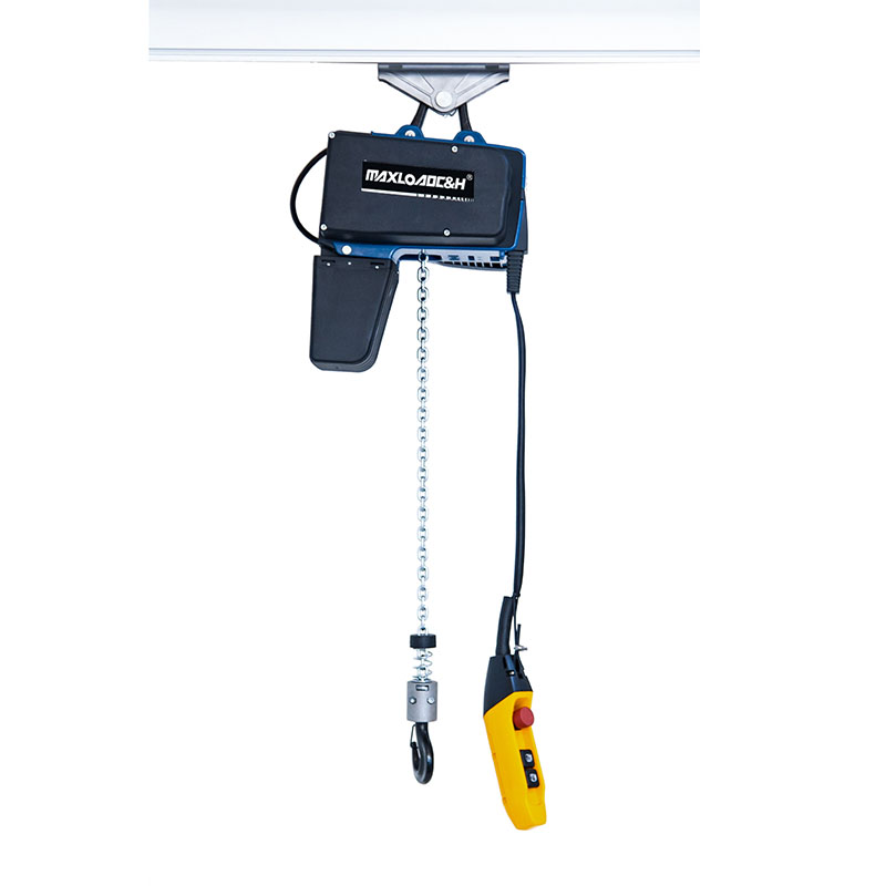
When pairing an electric hoist with a jib crane, headroom is often the first conflict to resolve. The effective lifting height in a building is usually limited, and the jib crane beam itself occupies a certain height, leaving very little space for the hoist. Here, low-headroom electric chain hoists have a clear advantage; their hooks can retract very close to the lower edge of the beam, freeing up more effective lift. Although wire rope electric hoists are robust and well-suited for heavy-duty, high-frequency use, they are less advantageous regarding headroom. It is necessary to calculate the drum diameter and hook assembly height and confirm that the hoist does not interfere with the upper and lower flange reinforcement plates of the jib beam when traveling to the root or the tip of the jib. Moreover, when the hoist travels to the outermost end and raises the hook to the upper limit, it must not strike the jib end plate or the slewing limit stop.
Lifting speed cannot be chosen solely from catalog parameters. Typically, chain hoists below 2 tons are common with a single speed, with a lifting speed of around 8 m/min. If used for applications such as mold closing or loading precision machine tools, this speed will cause significant swinging when stopping. Operators must then rely entirely on inching to level the load, which is laborious and compromises positioning accuracy. It is recommended to select a dual-speed hoist or variable frequency drive to achieve much smoother movement during load placement. In addition, the brake response must be observed. Some hoists use conical rotor motors or DC brakes; the amount of hook drop after a power loss must comply with standards. Under jib crane working conditions, a slipping hook can easily strike a workpiece or fixture.
Verification of Work Duty Class and Load Spectrum
Many people only focus on the lifting capacity. If a drawing indicates “2t”, a 2-ton hoist and a 2-ton jib crane are simply purchased, while the work duty class is ignored. A jib crane is a workstation crane that may perform hundreds of lifts per shift, for instance, beside an automotive parts stamping line, continuously picking and placing sheets. In such a scenario, even though the average load is below the rated capacity, the electric hoist and jib crane slewing mechanism should be selected according to a duty class of M5 or even M6 due to the high frequency; otherwise, gears, wheels and motor insulation will deteriorate rapidly. Conversely, if the crane is only used occasionally for maintenance, such as lifting a pump body, M3 is sufficient. Hoists with a higher duty class are more robust in their electrical controls, contactors and travel mechanism designs. Naturally, the overall cost will increase, but this is a necessary investment to prevent early failures. Sometimes the jib crane itself is designed for light duty, but because the hoist is changed to a heavy-duty one, attention must be paid to whether the fatigue strength of the jib beam meets the requirements; if necessary, the main beam section should be enlarged.
Matching the Running Rail and Hoist Trolley Wheels
The lower rail of a jib crane beam is typically an I-beam or the lower flange of a welded box beam. The electric hoist travel trolley runs directly on this flange. The slope and width of the I-beam flange must fall within the allowable range for the hoist trolley wheels. Common electric hoists are generally designed for standard I-beams from 20a to 45a, depending on the internal width of the wheel rim. If a non-standard section is used when fabricating the jib crane, or if the flange is thickened with welded cover plates, the slope and radius will change, leading to eccentric wheel wear, flange rubbing, and travel motor overload. On the installation site, the following checks can be performed: push the hoist by hand without a load and observe whether the wheel treads make uniform contact; drive the hoist electrically along the entire path under full load and measure the current or observe whether the travel speed drops abnormally. Such a drop indicates potentially excessive resistance.
The downward deflection of the jib beam directly affects hoist travel. A cantilever structure naturally has a larger deflection at the tip. When the hoist travels toward the tip, it is essentially “climbing a slope.” If the added slope resistance exceeds the traction force of the travel motor, the hoist will stop or slip. Deflection limits should be specified at the design stage, and pre-camber should be considered. On site, a level gauge can be used to measure the slope change curve of the hoist travel path, and track shims can then be adjusted or the beam re-aligned. In environments with significant vibration, attention should also be given to whether the unloaded hoist tends to slide on its own toward the lower end due to the track gradient; this situation calls for a travel motor with an electromagnetic brake or a rail clamp.
Control and Protection
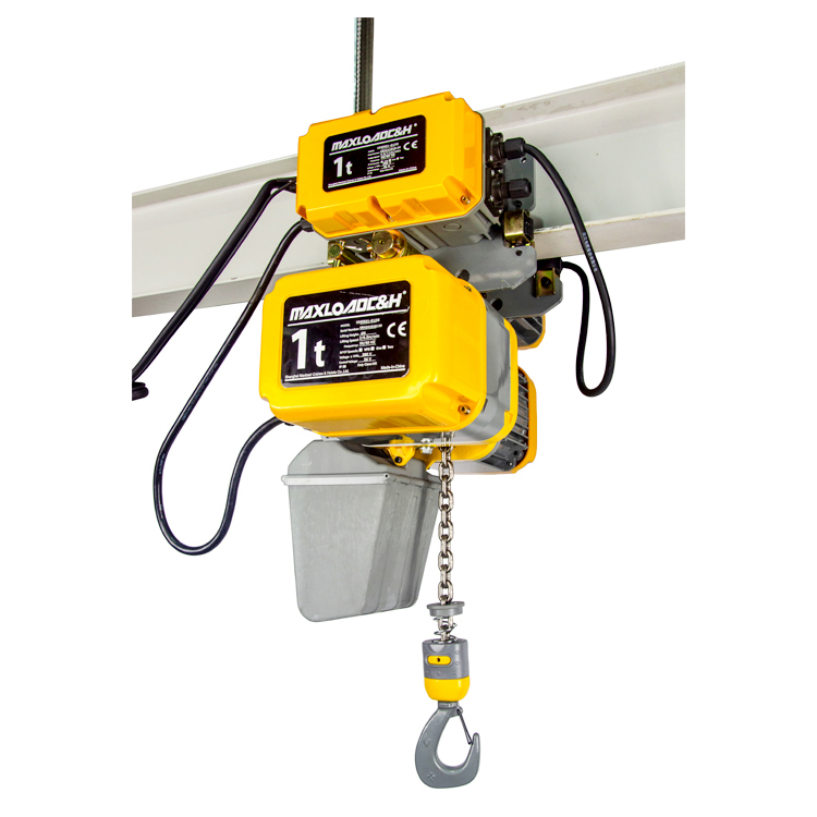
The coordination between the electric hoist and jib crane is generally controlled by either a pendant pushbutton station or a radio remote control. The pendant station hangs below the hoist. If the jib rotates frequently, the trailing cable can easily drag on the ground, becoming entangled and interfering with workpieces. Switching to a remote control can greatly improve the operating experience. Regardless of the method used, the emergency stop button must simultaneously cut off the power to the hoist lifting, hoist travel, and jib slewing motors. Additionally, upper and lower limit switches for lifting must be installed. Preferably, in addition to the hoist's own direct-breaking limit switch, a mechanical limit stop should be placed at the jib end as final protection. Travel limit switches can be added to prevent the hoist from running beyond the effective range of the jib. An overload limiter is essential: whether it is the friction clutch type built into the hoist or an electronic type, an overload test and calibration must be carried out after installation to ensure it triggers an alarm or cuts off lifting at 1.1 times the rated load.
Daily Inspection and On-site Details
After being put into service, the interaction between the jib crane slewing brake and the hoist travel must be incorporated into the daily inspection routine. For example, check the wear of slip ring brushes and whether carbon dust has accumulated inside the collector ring on a weekly basis. Check whether there is excessive lubrication on the running rail and whether the I-beam lower flange shows burrs or deformation. Verify that the hook safety latch is intact, bolted connections are not loose, and all anchor bolts of the jib column baseplate show no signs of elongation or loosening. Periodically test the jib deflection value under a reference load. If the deflection continues to increase, it may indicate overloading or fatigue of the steel structure, and an immediate evaluation is required.
Finally, manage the documentation for the jib crane and the electric hoist together, including factory records, change logs, and each inspection and maintenance report. Very often, these two pieces of equipment come from different suppliers and are maintained separately, creating a vacuum at the interface. Only by treating them as a single integrated system can they remain stable during frequent daily use and avoid those otherwise preventable downtimes.
 0086 156 1824 5535
 0086 156 1824 5535