Electric Hoist and Overhead Crane: Matching Logic and Systematic Application Analysis
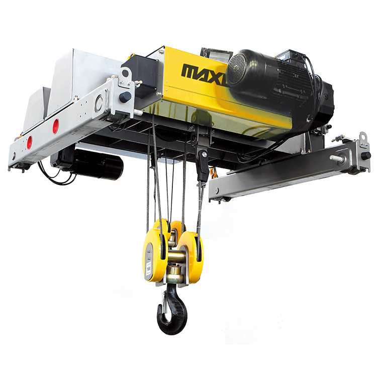
In the industrial lifting field, the electric hoist plays the role of the "executor", while the overhead crane (bridge crane) serves as the "carrier platform," providing spatial motion dimensions. The relationship between the two is not a simple installation overlay, but a systematic matching process that requires comprehensive consideration of parameters, structure, electrical systems, and operating conditions. Unfortunately, many users often treat lifting capacity as the sole criterion during procurement, neglecting the matching logic between the hoist and the crane. This leads to frequent problems after commissioning, such as running deviation, abnormal wear of metal structures, and electrical protection failures. Based on practical engineering experience, this article outlines the core points of pairing electric hoists with overhead cranes.
Matching Mainline: From Parameter Coordination to Mechanical Compatibility
The first step in selection is aligning the rated lifting capacity with the design load of the crane. It is not enough to only cover the maximum daily lifting weight; the dead weight of lifting slings and wire rope end attachments must also be included, while reserving a safety margin of 10% to 20%. The safety margin is not only a reflection of the overall machine design allowance but also directly affects the reaction of the hoist on the crane girder and trolley wheel loads. Insufficient margin leads to uneven distribution of trolley wheel pressure, causing the main girder to be in a state of long-term local overloading. This is closely related to the main girder cross-section selection and the stress state of welded rail joints.
Matching the duty classification is equally critical. The duty classification of electric hoists, according to ISO standards, ranges from M4 to M7 and must be consistent with the overall crane duty classification. An easily overlooked fact is that the duty classification is determined by both the load spectrum factor and the number of operating cycles. If a workshop performs dozens of lifts per day, each time at nearly the rated load, a hoist of M6 or higher should be selected, even if the tonnage is not large; otherwise, the motor and mechanical parts will suffer accelerated aging due to overheating. Conversely, if the crane is used only a few times a year for equipment maintenance, M3 to M4 is sufficient even with a larger lifting capacity. Over-specification would instead increase the burden on power supply capacity and structural dead weight.
The coordination of lifting and traveling speeds directly impacts lifting stability. The hoist's lifting speed and the trolley traveling speed must form a reasonable ratio with the crane's long-travel speed; otherwise, load sway will be significantly intensified when handling long or irregularly shaped workpieces. Generally, for conventional industrial scenarios, a traveling speed of 5 to 20 meters per minute suits most operations. For precision assembly or fragile goods, dual-speed or variable frequency drive models should be selected, using the low-speed gear to ensure positioning accuracy.
Scenario-Driven: The Boundary Between General and Specialized Solutions
A single hoist-crane combination scheme cannot be universal across all scenarios. Different industries have vastly different requirements for crane-hoist systems, and selection must be differentiated based on specific working conditions.
General Manufacturing and Warehousing Scenarios.
This is the most common application field. Machining workshops typically use M3 to M5 duty classification wire rope electric hoists paired with general single-girder overhead cranes. In heavy-duty scenarios of 5 tons and above, wire rope hoists outperform chain hoists of the same tonnage, thanks to the stable braking characteristics of conical rotor motors and the high load-bearing capacity of wire ropes. Warehousing and material handling require higher lifting speeds, so high-speed models above 16 meters per minute can be selected.
Metallurgical High-Temperature Scenarios.
The ambient temperature in metallurgical workshops often ranges from 40°C to 100°C. Under these conditions, the insulation aging rate of ordinary motors rises exponentially. Configurations specialized for metallurgy require motors with forced cooling systems and chains (or wire ropes) using high-temperature resistant grease. More critically, the lifting mechanism of a metallurgical hoist is usually equipped with a dual braking system and overheat protection devices to meet the extremely high safety requirements for handling molten metal.
Chemical and Flammable/Explosive Environments.
Explosion-proof hoists and explosion-proof overhead cranes can be paired to form a complete explosion-proof lifting and traveling system. The explosion-proof hoist uses a fully sealed structure, designed according to flameproof or increased safety standards from the motor housing, junction box, to the control circuit, preventing sparks during operation. The crane side also needs matching explosion-proof electrical components, including explosion-proof control cabinets and explosion-proof limit switches. The entire machine must pass the corresponding explosion-proof certification. Additionally, the metal parts of the hoist need galvanizing or anti-corrosion coating treatment.
Cleanroom Scenarios.
In industries like semiconductors and biomedicine, the crane-hoist system has strict cleanliness requirements, potentially up to Class 100. Cleanroom hoists typically use stainless steel housings, completely sealed drive mechanisms, and chains or wire ropes with special surface treatment to reduce friction particle shedding. Traveling wheels must use low-dust-generating materials to avoid generating particles on the track. Such scenarios also demand higher running smoothness, making variable frequency drives almost a standard feature.
Engineering Practice for Installation and System Commissioning
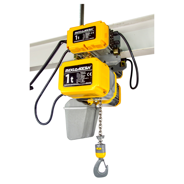
Installing an electric hoist on the crane's main girder is not just a simple hanging and fixing job; it involves multiple steps of mechanical connection, electrical wiring, and overall machine joint debugging.
Electrical System Integration.
The electrical interface between the hoist and the crane is a prerequisite for the reliable operation of the entire system. Power circuits, control circuits, and lighting circuits must be strictly divided in wiring, with conductors of different voltage levels separately fed through conduits to avoid signal interference or short-circuit risks. All connection terminals must be crimped securely and properly insulated to prevent loosening and arcing. The motor winding insulation class should not be lower than Class F, and the protection class should not be lower than IP54. The length of the flexible cable travel section should be 15% to 20% more than the crane movement distance, to compensate for expansion and contraction during operation.
System-Level Verification of Safety Devices.
The joint commissioning after electrical system integration is the last line of safety defense. The upper and lower limit switches must be tested repeatedly under no-load conditions to confirm that they can immediately cut off the lifting circuit power upon triggering. The overload protection device should issue a warning when the load reaches 90% of the rated value and automatically cut off the power when it exceeds 110%. The emergency stop button should use a dual-circuit hardwired design to ensure instantaneous disconnection of all power supplies upon activation, rather than relying solely on a software logic shutdown.
Rail Gnawing and Service Life: Deep-Seated Issues of the Traveling System
"Rail gnawing" (wheel flange rubbing against the rail) is the most common and easily overlooked fault in electric hoist bridge cranes. Its symptoms are continuous abnormal friction between the wheel flange and the rail side, accompanied by metallic noise, flange wear, and accumulation of debris on the rail side. The common causes fall into the following three categories.
The first category is rail installation accuracy deviation.
Exceeding gauge tolerance, a height difference between the two sides exceeding 10 mm, large straightness deviation of the rail, or joint misalignment will all disrupt the normal mating relationship between the wheel and the rail. Uneven settlement of the rail foundation and deformation of the crane beam can indirectly lead to similar problems.
The second category is an abnormal condition of the wheel assembly itself.
Excessive horizontal or vertical skew of the wheel causes the flange to passively bear lateral forces. When the wear difference between the driving and driven wheels exceeds 3 mm, the rotation speed of the wheels on both sides is the same, but the travel distance differs, causing the crane body to twist and subsequently gnaw the rail.
The third category is the synchronization problem of the electrical drive.
Unequal rotation speed of the driving motors on either side of the crane, excessive power deviation, or improper setting of the variable frequency drive parameters can lead to unbalanced driving forces on both sides of the crane body, causing running deviation. Inconsistent braking torque of the brakes on the same mechanism can also cause the entire crane to skew to one side during braking, aggravating local abnormal wear between the flange and the rail.
Remediation requires targeted measures: use total stations and levels to detect track parameters and adjust or replace tracks that exceed tolerances; disassemble the wheel assembly to measure wear and correct skew; implement an automatic deviation correction control system, using separate variable frequency drives to control the motors on each side, combined with displacement or angle sensors to achieve real-time compensation of the running speed.
 0086 156 1824 5535
 0086 156 1824 5535