Precision Match: Electric Hoist and Overhead Crane
Not Just "Bolt It On"
Many first-time buyers of lifting equipment have a simple assumption: pick an electric hoist, hang it on the crane trolley, connect the power, and it’s ready to go. Twenty years ago, this idea might have been more or less acceptable – operating conditions were relatively uniform back then and equipment had plenty of reserve capacity. Today, however, factory headroom is increasingly tight, production cycles are more demanding, and the objects being lifted range from rough blanks to precision assemblies. Under these conditions, the “just bolt it on” approach has already planted far too many hidden problems.
The core issue is that an electric hoist does not work as an independent device. When it forms a system with an overhead crane, the hoisting movement and the travel movements are superimposed on each other, and the load characteristics change accordingly. Matching the hoist with the crane involves not only mechanical aspects such as rail compatibility and wheel load distribution, but also electrical aspects such as power coordination and control logic. It is also constrained by a variable that is too easily overlooked: the duty classification.
Ⅰ. Duty Classification: A Parameter More Important Than “How Many Tons”
The most common question during equipment selection is “What’s the capacity?” – meaning the rated lifting capacity. But capacity is only a static parameter; it does not reflect the actual working intensity of the equipment. If the duty is not matched to the application, the motor is likely to overheat and the gearbox to show abnormal wear within three months.
The parameter that captures this difference is the “duty classification”. According to ISO standards, duty classifications range from M3 up to M8, corresponding to FEM classifications from 1Bm to 5m. The classification is determined by two dimensions: the load spectrum factor and the number of working cycles.
As a rough engineering guide:
M3/M4 (FEM 1Am/1Bm): Suitable for low-frequency applications such as maintenance and installation workshops, where the equipment is used a few times to a dozen times a day, mainly with light loads. A hoist selected to M3 paired with a single-girder crane is the most common configuration for small and medium-sized workshops.
M5 (FEM 1Cm): Suitable for machining shops and assembly lines, with moderate frequency and loads close to the rated value. This classification is a watershed for factory installations – equipment rated below M5 used on a production line will show a marked increase in failure rates.
M6 and above (FEM 1Dm–3m): Suitable for continuous-duty applications such as warehouses, conveyor lines, and even metallurgical or foundry operations. In these cases, not only must the hoist itself be upgraded, but the crane’s bridge and trolley travel mechanisms must also be raised to the same duty classification; otherwise, a weakest-link effect will compromise the entire system.
A frequently made mistake is to select a hoist based solely on lifting capacity while ignoring the design duty classification of the crane itself. If the duty classification of the crane bridge girder and trolley rail is lower than that of the hoist, the service life of the whole machine will be shortened even if the hoist can withstand the work. During selection, it is essential to ensure that the duty classifications of the hoist, trolley and bridge are matched within the same range.
Ⅱ. Structural Coupling between the Hoisting Mechanism and the Crane Bridge Girder
Mechanically, the combination of an electric hoist and a crane follows two main routes: the hoist-type crane and the winch-type crane. These are not merely two different names for the same thing – the difference lies in the fundamental driving method of the hoisting mechanism.
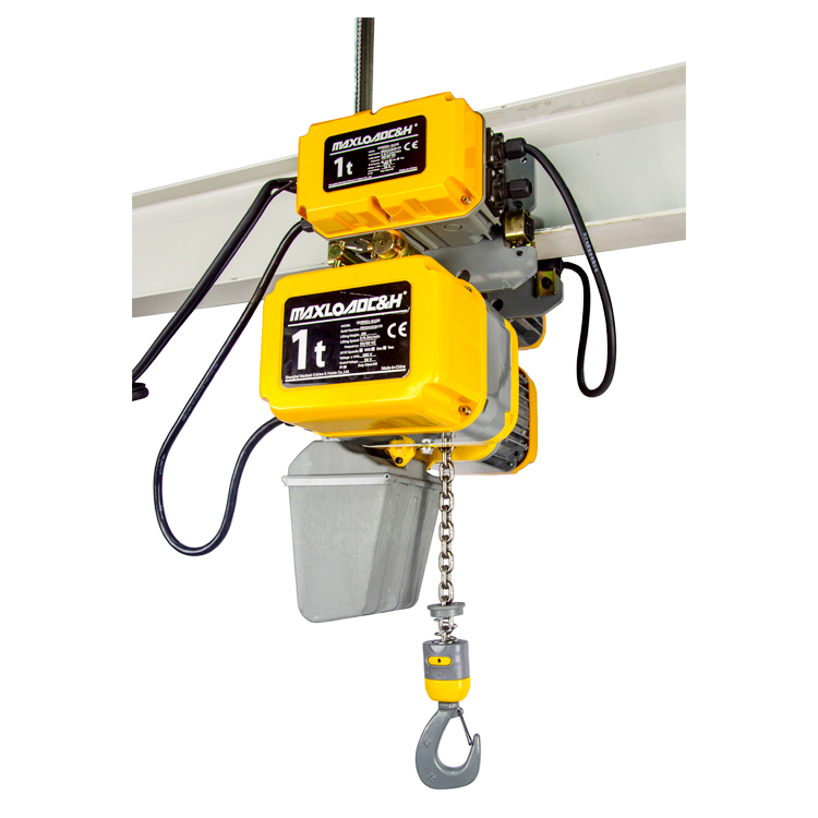
A hoist-type crane uses an electric hoist as its core lifting mechanism, with the motor, gearbox, drum and brake integrated into a compact module that is directly suspended from the crane trolley or the bridge girder. Its advantages are a compact structure, light deadweight, and easy installation, giving it an outstanding price-performance ratio in small and medium-capacity applications. The disadvantage is that the rope drum capacity is limited, and lifting height is correspondingly constrained, though this can be mitigated by a low-headroom design.
For most general manufacturing workshops, the hoist-type crane is the mainstream choice. Even with this type, however, the way the electric hoist connects to the main girder is worth careful attention. The normal practice today is for the hoist to be mounted on a travelling trolley that sits astride the main girder rail, with the trolley frame guided by the wheel treads and flanges on the rail. The rail profile must strictly match the wheel track gauge and tread width of the hoist trolley; otherwise, flange wear will be accelerated, and rail binding may even occur.
Ⅲ. The Travelling Trolley: An Easily Overlooked Intermediate Link
The travelling trolley is the interface between the hoist and the crane rail. Its role is not only to allow the hoist to travel along the rail, but also to distribute the wheel loads and ensure smooth running stability. The wheel gauge of the trolley must match the web width of the rail; once mounted, there must be no obvious play. When adjusting the wheel gauge, it is necessary to first measure the actual web dimensions of the I-beam rail and then adjust the spacing of the trolley wheels accordingly, so as to ensure that the wheel treads make full contact across the full width of the rail.
The drive method for the trolley also matters. A hand-pushed or hand-geared trolley is suitable for a maintenance hoist used only occasionally; for production-line applications that require frequent transverse movement, a motorized travelling trolley should be selected. The motorized trolley and the hoist can share a single radio remote control system, using one transmitter to control both lifting and travelling simultaneously. However, when wiring, it is essential to ensure that the control circuit logic is correct to avoid signal interference.
The choice of trolley travel speed also requires a trade-off. The higher the speed, the higher the handling efficiency – but the requirements for rail flatness and end stop buffer devices also become higher, and the positioning accuracy will decrease. For precision assembly applications, a variable-frequency drive trolley can be used to achieve slow-speed, precise positioning; for general material transport, a single-speed or dual-speed trolley is sufficient.
Ⅳ. Practical Calculation of Headroom and Lifting Height
“Lifting height 6 metres” is a common parameter given on a data sheet, but the height actually available in service is often less than this figure. The reason is that the hoist’s own structure occupies a certain amount of height space.
Actual effective lifting height = Rail elevation − Hoist headroom dimension − Lifting tackle height − Workpiece height − Safety lower limit distance.
The headroom dimension refers to the height from the rail tread to the upper limit position of the hook, which is taken up by the hoist body itself. A low-headroom hoist compresses this dimension to a minimum through a compact design, which can significantly increase the effective lifting space when the factory roof height is limited.
At the procurement and selection stage, it is advisable to first calculate these four or five parameters and then work backwards to determine the required hoist headroom classification and lifting height specification, rather than simply reading the nominal value on the nameplate. The cost of getting this calculation wrong is considerable – once the equipment is installed and it is found that the lifting height is insufficient, the cost of modifying the rail elevation or replacing the hoist is much higher than the extra care taken during selection.
Ⅴ. Electrical Integration and Standard Safety Devices
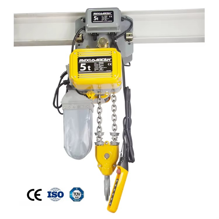
The electrical integration of an electric hoist and a crane is essentially about coordinating two motor systems: the hoisting motor is responsible for hook lifting and lowering, while the travel motors are responsible for transverse and longitudinal movement. Taking a common 10-tonne hoist as an example, the hoisting motor power is approximately 7.5 kW, and the trolley travel motor power is approximately 0.65 kW × 2. These motors are typically conical-rotor brake motors, which have a built-in mechanical braking function that automatically applies the brake when power is cut off.
In terms of control, the use of variable frequency drives is becoming increasingly common. Variable-frequency control can eliminate the load sway problem associated with conventional hoists during starting and stopping, achieving smooth starting and stopping and precise positioning – this is particularly important on assembly lines where a workpiece needs to be accurately placed into a fixture. The parameter settings of the VFD must match the motor power and reduction ratio; the minimum stable operating frequency under both no-load and full-load conditions can typically be as low as 1 Hz or less.
In terms of safety devices, an electric hoist must be equipped with at least the following as standard:
Upper hoisting limit switch: Automatically cuts off the hoisting circuit when the hook reaches the upper limit position, preventing the wire rope from being over-wound and causing an accident.
Travel limit switches: Required in both the bridge and trolley directions to prevent the travel mechanisms from running beyond the extent of the rail.
Overload limiter: Automatically cuts off the hoisting movement or issues an alarm signal when the load exceeds the rated value.
Rail end buffer devices: Resilient buffers installed at each end of the I-beam rail to prevent the hoist from derailing or colliding with the end stop due to inertia.
The reliability of these devices directly affects the safety of the entire lifting system, and it should be confirmed during selection that they are part of the standard supply, not optional extras.
Ⅵ. Installation and Commissioning: Three Indispensable Tests
Before a newly installed or overhauled electric hoist crane system is officially put into service, it must pass three tests: no-load trial run, static load test and dynamic load test. This sequence must not be reversed, and no test can be skipped.
During the no-load trial run, the hoist is made to travel the full length of the rail several times, observing whether the movement is smooth, whether there is any jamming or abnormal noise, and whether the limit switches are triggered reliably. Only when it is confirmed that there is nothing abnormal under no-load conditions should the static load test proceed: a test load of 125% of the rated capacity is lifted, kept about 100 mm above the ground, and held for 10 minutes, while checking whether there is any permanent deformation of structural components and whether the brake can hold the load stably. Finally comes the dynamic load test: under the rated load, repeated lifting, lowering and travelling operations are performed to verify the combined reliability of the mechanical drive and electrical systems.
These three tests are not a matter of going through the motions. In practice, many potential problems – such as insufficient bolt preload, misalignment of wheel-rail contact, and brake clearance outside tolerance – are brought to light precisely during this stage. Skipping these tests and putting the equipment directly into production amounts to leaving the problems to be discovered during daily operation, at a much higher cost.
Conclusion
The pairing of an electric hoist and an overhead crane, in the final analysis, is the embodiment of “systems thinking”. Choosing a good hoist and choosing a good crane does not automatically result in a good system. The matching of the intermediate interfaces – from duty classification to rail dimensions, from headroom calculation to electrical coordination – determines how much of the design capacity the final installation can actually deliver. For the user, rather than piecing together components from multiple suppliers, it is better to start from an overall system engineering perspective and ensure that the hoist, trolley, bridge and safety devices form a closed loop at the technical parameter level.
After all, the value of lifting equipment is not reflected on a quotation sheet; it is built up, day by day, in the timeline of stable, trouble-free operation.
 0086 156 1824 5535
 0086 156 1824 5535