Collaborative Application and Selection Practice of Jib Cranes and Electric Hoists
In discrete manufacturing, equipment maintenance, material handling and other processes, the fixed-point handling unit composed of a jib crane and an electric hoist is perhaps the most inconspicuous yet most relied-upon equipment in the workshop. Its task is clear: within a limited sector-shaped or circular area, quickly and accurately deliver workpieces, molds, and material boxes to designated positions. Although the combination seems simple, achieving both reliability and flexibility in production requires coordinating the mechanical structure and electrical control during the design stage.
Structure and Matching
Common jib cranes include three types: free-standing column-mounted, wall-mounted, and mobile. The column-mounted type is the most widely used; it does not rely on building columns and independently bears all overturning moments. The wall-mounted type is used where column spacing or wall conditions permit, effectively saving floor space. The mobile type can travel along rails as a complete unit, suitable for cross-station operations. The electric hoist can travel along the track on the lower flange of the jib arm or be fixed at the arm tip for point lifting. The former, combined with arm rotation, provides polar coordinate coverage, while the latter requires more frequent arm rotation to adjust the drop point.
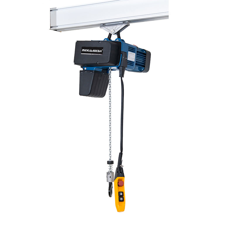
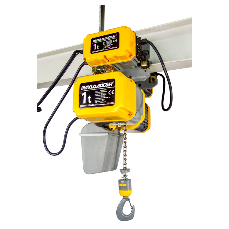
The hoist itself can be divided into two main categories: wire rope and chain. Wire rope hoists have advantages in lifting capacity and lifting height, and their working class is more easily achieved at M5 or above, making them suitable for frequent, heavy-duty conditions. Chain hoists have a compact structure, high cleanliness, and good tolerance to frequent inching impacts, making them more common on assembly lines and in clean rooms. Whichever type is chosen, if smooth lifting and precise positioning are desired, it is best to equip it with a variable frequency drive (VFD) to achieve slow positioning through low speeds, avoiding sway caused by abrupt stops. When the jib arm is equipped with electric rotation, the synchronized variable frequency control of rotation and hoist travel can significantly improve the working cycle.
Key Points of Load Calculation
The place where deviation is most likely to occur in a combined design is often not the maximum lifting capacity, but the omission of the hoist's own weight on the jib arm in calculations. Suppose a column-mounted jib with a span of 5 meters is equipped with a chain hoist weighing about 80 kg, and the mass of hooks and lifting attachments must also be added. The bending moment produced by these concentrated moving loads at the arm tip can be more prominent than the rated load, especially when the hoist is near the arm tip, where deflection increases sharply. This should be used as the design input to check the bending stress and deflection of the arm cross-section. Generally, the vertical deflection of the cantilever end under 1.1 times the rated load should not exceed 1/500 to 1/400 of the arm length, and a stricter value should be taken for high-frequency use or precision assembly stations.
The load combination for the hoisting mechanism cannot simply take the rated lifting capacity. Factors such as the lifting dynamic coefficient, travel impact coefficient, and occasional light-load high-speed impacts must be considered. Determining the working class according to the actual operating conditions is fundamental to preventing fatigue of the steel structure and rapid wear of the mechanism. Foundation design must not be neglected either. The column base plate and embedded anchor bolts must be able to resist the maximum overturning moment. The concrete foundation weight and ground bearing capacity must have sufficient margins to prevent foundation loosening under repeated alternating loads.
Typical Working Conditions and Configuration
At many CNC machine tool loading and unloading stations, a layout like this is often seen: a column jib is erected next to the machine, equipped with a chain hoist with dual-speed or VFD lifting. The spreader picks up the blank, lifts it quickly, the arm rotates manually or electrically above the machine door, and the hoist descends at an extremely slow speed until the workpiece is securely placed in the fixture, with positioning accuracy down to the millimeter level. If the station cycles more than 30 times per hour, at least M5 working class should be selected, with motor insulation class F and thermal protection configured. For maintenance areas that need to lift and flip molds, a wall-mounted jib is often more suitable. A chain hoist with twin hooks can be selected to assist in flipping in the air, avoiding safety risks associated with ground operations.
For production lines with higher automation requirements, the jib rotation and the hoist's three-axis movement will all be integrated into PLC control, achieving semi-automatic or fully automatic loading through encoders and limit switches. At the same time, laser distance sensors or mechanical anti-collision devices are equipped to prevent interference between the arm and surrounding equipment. Under this configuration, the routing of cables, sensors, and mechanical structures must consider slip rings and through-holes for 360° arm rotation, while ensuring reliable grounding.
Installation and Foundation Requirements
The accuracy of on-site installation directly affects whether the hoist runs smoothly and whether the jib arm vibrates. After the column is in place, the verticality deviation must not exceed 1/1000 of the column height. The base plate and foundation surface should be leveled with shims, and the secondary grouting must be dense. The butt joints of the jib arm track must be smooth, and the joint gap and height difference must be strictly controlled; otherwise, the hoist wheels will experience impact and rail gnawing when passing, which can eventually lead to plastic deformation or cracks in the flange. The bolt pre-tightening force between the arm and the slewing bearing should also be verified with a torque wrench to prevent loosening after long-term operation.
Power supply generally uses flat cables routed along the side of the arm with a cable carrier. For those capable of continuous 360° rotation, a collector slip ring must be configured. The slip ring contacts must ensure no overheating under the hoist motor's stall current, and the enclosure protection class should at least reach IP54, depending on on-site dust or water splashing. In addition, the control circuit and power circuit must be isolated. Emergency stop buttons should be arranged at both the operation pendant and the column control box, so that they can be quickly activated in an emergency.
Electrical and Safety Integration
The hoist's own upper/lower limit switches and weight-operated limit switches are standard, but this is not enough. An overload limiter must be added to the crane. When the load reaches 1.05 to 1.1 times the rated value, the lifting will be automatically cut off. The setting can be fine-tuned if impact loads are unavoidable, but it must never be bypassed. For electrically rotating jib arms, rotation angle limits and deceleration stop positions need to be set to prevent hitting the column or walls. The slow positioning provided by VFD can significantly reduce mechanical impacts on end stops and buffers, extending the structure's life.
It is worth mentioning that if both the hoist travel and jib arm rotation participate in the automatic cycle simultaneously, the program needs to design interlocks and acceleration/deceleration ramps to avoid direct direction changes from high speed. Otherwise, load sway can cause wire rope disorder or chain bag damage, and can easily lead to sensor misjudgment. It must be ensured that in any fault mode, the brake can engage reliably and no load slipping will occur.
Common Misconceptions and Countermeasures
In practice, several common trade-off biases are seen: First, thinking that a longer jib arm is more convenient, while ignoring the reduction in effective lifting capacity under a long arm, resulting in an undersized hoist that cannot actually lift the nominal load. Second, focusing only on the hoist brand and price, while neglecting the working class, using an M3 class hoist in a metallurgical or two-shift machining environment can lead to abnormal gear wear in less than half a year. Third, ignoring rotational inertia, during manual rotation, the operator pushes hard, causing the load to swing and hit the machine tool, and during electric rotation, there is no deceleration buffer, causing the column to shake. These problems should be solved once and for all in the early technical scheme through reasonable rotational damping, VFD soft start/stop, and selection verification. In addition, the supplier needs to provide a complete design, including the column base, embedded anchor bolts, and track, to avoid a disconnect between foundation construction and the upper equipment.
As a mature workstation handling solution, the reliability of the coordinated work between the jib crane and the electric hoist ultimately depends on the full-chain control from foundation design, load analysis, mechanism matching, and electrical safety integration. Only when every link provides reasonable parameters according to the actual working conditions can this simple equipment truly realize flexibility, safety, and long service life. In the future, with the popularization of condition monitoring sensors, real-time detection of hoist motor current, vibration, and wire rope wear, uploading to the Manufacturing Execution System (MES), will further help identify early hidden dangers, shifting production assurance from post-breakdown repair to proactive intervention.
 0086 156 1824 5535
 0086 156 1824 5535