Electric Hoist and Jib Crane
In workshop workstations, assembly lines, or equipment maintenance areas, jib cranes are widely used due to their point coverage and light slewing action. Installing an electric hoist onto a jib crane may seem like a simple “hook it on” combination, but in reality, to ensure long-term safe, precise, and efficient operation of the system, there are numerous engineering details that are easily overlooked during selection, rail matching, electrical integration, and installation and commissioning. In actual projects, many issues such as jerky movement, load drifting, cable breakage, and even early structural fatigue stem from improper matching and integration at the outset. From a system design perspective, the following key points should be considered when matching an electric hoist with a jib crane.
Ⅰ. Structural types of jib cranes and prerequisites for electric hoist adaptation
Common jib crane structures include column-mounted, wall-mounted, and portable types. The column-mounted jib crane is fixed to the ground via a foundation, with the beam rotating around the column to cover a circular area. The wall-mounted jib crane relies on factory building columns or dedicated wall rails, allowing movement along the wall while the boom itself can rotate. The portable jib crane has a movable base, suitable for temporary workstations or light loads.
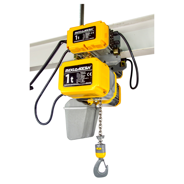
Different types of jib cranes have different requirements for the electric hoist. For column-mounted and wall-mounted jib cranes, the beam typically uses an I-beam cross-section, and the electric hoist is suspended from the lower flange of the I-beam via a trolley. The tread width and flange clearance of the hoist’s wheels must be compatible with the width, slope, and fillet radius of the I-beam’s lower flange. If the I-beam flange is too narrow while the hoist’s wheels are too wide, or if the flange clearance is insufficient, jamming and uneven wear will occur during operation. Additionally, for wall-mounted jib cranes where the beam travels transversely, the hoist trolley must be able to withstand additional inertial forces caused by beam movement, making wheel flange and side guide wheel design more critical.
The rated lifting capacity of typical jib cranes ranges from 250 kg to 5 tons. Chain electric hoists, due to their compact structure and low headroom, are highly suitable for jib cranes. They occupy minimal height and preserve maximum effective lifting height, which is especially advantageous when the space between the I-beam lower flange and the floor is limited. For higher capacities or lifting heights, wire rope electric hoists may also be used, but attention must be paid to their larger drum length, which may affect the approach distance at extreme positions.
Ⅱ. Key parameter matching considerations
Matching a jib crane with an electric hoist requires verifying a series of parameters, not just lifting capacity.
First, confirm the I-beam rail specification. The electric hoist trolley is typically designed for a specific range of lower flange widths. Beyond matching dimensions, the local bending stress and root stress of the lower flange under full load must be calculated to prevent plastic deformation. In field practice, undersized I-beams have been known to cause trolley wheels to indent the lower flange under heavy load, leading to a sharp increase in running resistance.
Headroom and hook position are also crucial. The “under‑beam height” shown on jib crane drawings is not equivalent to the effective lifting height. The electric hoist itself has a certain structural height—the distance from the hook throat to the I-beam bottom when the hook is at its upper limit. Where ceiling height is limited, the highest and lowest hook positions must be calculated based on the hoist’s dimensional envelope. Also, consider the change in beam camber under full load: a loaded cantilever beam will deflect. If the hoist stops at the boom tip, the rail tilts downward slightly. If the hoist’s travel mechanism lacks a holding brake, it may drift slowly. This should be addressed during design by presetting camber or slope restrictions.
During slewing, how the electric hoist’s power cable follows the motion is another easily underestimated detail. Column-mounted jib cranes are often equipped with a central collector ring to supply power to the hoist on the boom. However, the hoist’s own travel requires its power cable or festoon system to move along the boom beneath it. These two motions must not interfere. If the hoist cable simply hangs loose like an ordinary pendant cable, when the jib rotates through a large angle, the cable may snag on the column or diagonal brace, or be pulled and broken. A proper solution is to route the travelling cable through a cable carrier or wire rope track, keeping it compactly along the side of the I-beam, and to provide sufficient cable slack and guidance below the collector ring so that no tight bends or pulling forces occur at any slewing angle or hoist position.
The match of lifting and travel speeds also affects operating efficiency and positioning accuracy. Jib cranes are often used for point‑to‑point handling, such as machine tool loading/unloading or die changing, requiring speed but without large load swings. Chain electric hoists typically offer two‑speed or inverter‑controlled variable speed, allowing precise positioning at low speed during lifting and smooth acceleration/deceleration during travel to suppress pendulum motion. If a single‑speed hoist is used, combined with the inertia of the jib structure and load swing, positioning becomes very difficult, potentially impacting nearby equipment and operators.
Ⅲ. Electrical control and safety interlock integration
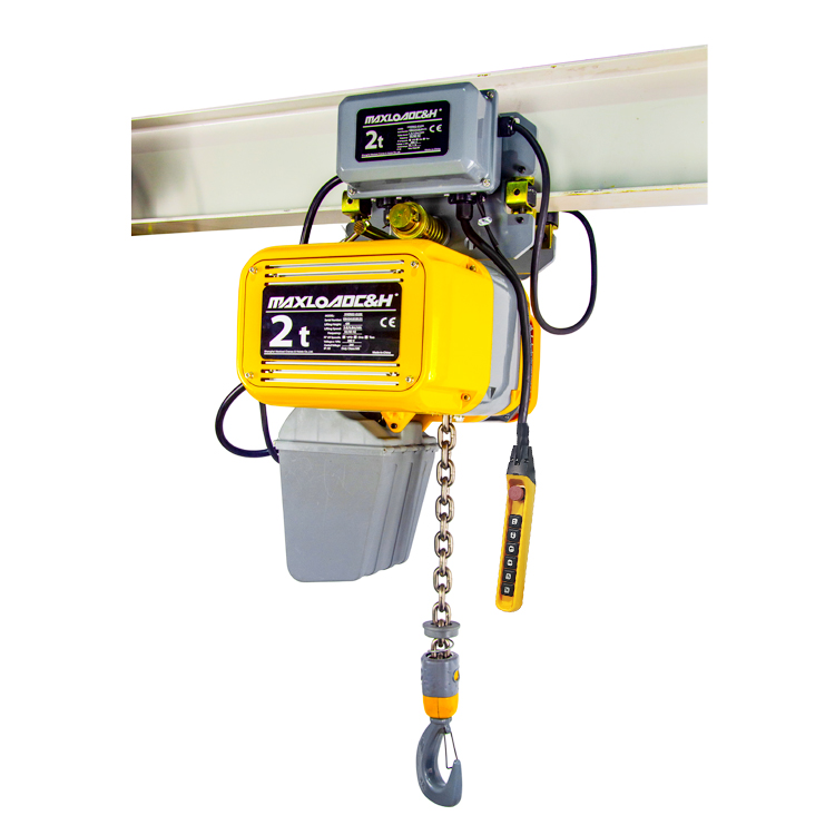
Electric hoists on jib cranes are commonly controlled by either a pendant push‑button station or a wireless remote. The pendant station connects directly to the hoist at low cost, but the cable hangs below the hoist, requiring consideration of both cable take‑up during hoist travel along the beam and cable drag during jib slewing. In practice, spring‑loaded reels or balancers keep the cable neat. Wireless remote control eliminates cable constraints, offering greater convenience for multi‑degree‑of‑freedom operations (slewing and hoist travel) and can integrate emergency stops and collision avoidance.
For high‑use, high‑efficiency stations, electrically driven jib slewing can be considered, with the slewing motor control integrated into the hoist control system to achieve coordinated “slew‑travel‑lift” operation. Where boom‑tip collision is a concern, limit switches can be installed at the slewing extremes, wired in series with the slewing drive circuit. Similarly, positive stops and deceleration limits should be provided at the boom ends to prevent the hoist from running off the rail. No travel limit device should rely solely on the hoist’s internal upper/lower limits while neglecting end‑of‑structure protection.
Another easily overlooked electrical integration point is coordination between phase‑loss protection and overload protection. The electric hoist itself has motor protection, but if the jib crane has powered slewing, it should also have independent overload and limit protection. The control power for both parts typically comes from the same upstream switch. It must be ensured that when one part trips due to a fault, the other part can stop safely, avoiding a scenario where the hoist is suspended with a load while the jib slewing is out of control.
Ⅳ. Common installation and commissioning issues and solutions
During installation, the quality of joints in the I‑beam rail directly affects smooth hoist travel. Joint mismatch, gaps, or weld spatter on the lower flange must be carefully addressed and ground smooth. Where possible, a small electric flat car can be used to run on the track. During commissioning, no‑load running tests must be followed by full‑load tests to verify the slewing flexibility of the entire jib and the travel resistance of the hoist. Special attention should be paid to whether the boom tip deflection under full load meets design values, and whether the hoist trolley tends to accelerate toward the tip or the center. If drifting occurs, it can be corrected by adjusting the travel motor brake or adding anti‑drift devices.
Dynamic and static load tests are key to identifying problems. Some integrators perform load tests only on the hoist, ignoring the overall jib crane structure. The correct approach is to hoist 1.25 times the rated load (dynamic) while travelling full span and slewing, then perform a static load test at 1.5 times the rated load, holding to check for plastic deformation, weld cracks, or abnormal slewing bearing noise. Only then can the safety of the entire system be confirmed.
Ⅴ. Technical emphasis in typical applications
In die‑change areas, a jib crane paired with a low‑speed, stable chain electric hoist enables precise zero‑to‑zero lifting of molds near injection or press machines; variable‑frequency lifting prevents damage to guide pins. On assembly lines, multiple column‑mounted jib cranes arranged in rows each cover a workstation, with electric hoists controlled by wireless remotes, allowing operators to walk and operate for blind‑spot‑free lifting. In maintenance pump rooms or fan rooms, a wall‑mounted jib crane with an electric hoist allows heavy items to move along the wall and swing over equipment, avoiding the floor space needed for permanent monorails. Portable jib cranes are mostly used at maintenance points requiring occasional lifting assistance, typically with a lightweight chain hoist that one person can push into position and operate.
In any application scenario, it is recommended to treat the jib structure, hoist rail, hoist unit, power supply system, and control system as an integrated package for selection and testing, rather than piecemeal assembly. When the supplier has complete design capability and type‑test verification, the subsequent safety and efficiency of the system are more assured. For workshop managers, a thorough understanding of these matching principles will help reduce misuse and allow the jib crane to deliver its flexible, safe, and efficient value beside the production line.
 0086 156 1824 5535
 0086 156 1824 5535