Supporting Overhead Crane: Key Points for Selection, Installation, and Integration
In industrial workshops, warehousing and logistics, and equipment manufacturing sites, the combination of an overhead crane and an electric hoist is almost the most common material handling solution. Among them, the wire rope electric hoist has become the preferred hoisting mechanism for overhead cranes due to its high lifting height, wide speed range, and compact structure. However, simply hanging a hoist onto the crane is not enough – the proper matching of the two directly determines overall efficiency, safety, life, and process adaptability. Based on practical project experience, the following key points are outlined in terms of integration form, parameter matching, electrical control integration, installation and commissioning.
Integration Forms and Load-Bearing Structures
Overhead cranes are classified by their main girders into single-girder and double-girder types. Single-girder cranes mostly use the bottom flange of an I-beam as the running track for the hoist trolley. The hoist is suspended via a traveling trolley, with the wheels directly straddling the I-beam. This form is sensitive to headroom clearance. In retrofit projects, especially, insufficient rail top elevation often results in insufficient lifting height. In such cases, a low‑headroom design wire rope hoist can be selected, with the hoisting mechanism and traveling trolley arranged compactly, gaining several hundred millimeters of lifting space under the same rail.
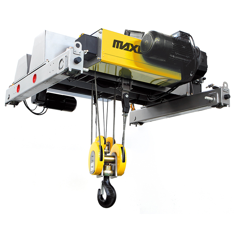
On double-girder cranes, the hoisting mechanism is mounted on a trolley frame that travels along the two main girder rails. The wire rope hoist can be fixed-mounted or of the traveling‑trolley type. For long workpieces or balanced lifting applications, dual-hoist tandem lifting is common. In such cases, the two hoists require electrical synchronization or a rigid mechanical connection; the rated lifting capacity sum must be greater than the load, and neither hoist may be overloaded. Regardless of the form, the joint dimensions and bolt hole patterns at the connection between the hoist and the main girders must match the crane’s trolley frame at the design stage – field reaming or adding shims will compromise the load‑bearing condition.
Key Parameter Matching Considerations
The most easily overlooked factor is the continuity of duty classification. The complete crane is assigned a duty class based on its frequency of use and load spectrum. As the core mechanism, the hoist’s mechanism duty class must match that of the crane. If a wire rope hoist with a lower duty class is selected, field symptoms will include accelerated wire rope breakage and strand failure, excessive brake wear, and burnt contactor tips. The correct approach is not to look only at the nominal rated lifting capacity, but to estimate the total number of operating cycles based on daily operating time and the actual load spectrum, then select a hoist with the corresponding mechanism class.
Hoisting speed and lifting capacity must be coordinated with the crane parameters. For long‑span cranes, the crane traveling speed is relatively high. If the hoisting speed is too slow, the positioning rhythm is slowed, increasing overall cycle time. Conversely, in precision assembly stations, a high‑speed hoist may reduce micro‑positioning accuracy due to excessive inertia – in such cases, a two‑speed or frequency‑controlled hoist is preferable. When replacing an existing hoist in a plant, the actual rail tread width, wheel load, and curved rail radius must be measured to ensure compatibility of the traveling trolley’s wheel set with the existing rail. The bending stress on the I‑beam bottom flange under full‑load concentrated wheel load must also be checked to avoid local plastic deformation and rail gnawing.
Compared with chain hoists, wire rope hoists are more suitable for conditions where lifting height exceeds 12 meters and speed exceeds 8 m/min. They also provide greater safety redundancy – wire rope breakage is preceded by detectable wire fractures, whereas chain breakage often occurs suddenly. However, in clean‑room environments, maintenance‑free wire ropes or enclosed dust‑proof constructions with corresponding guards should be considered.
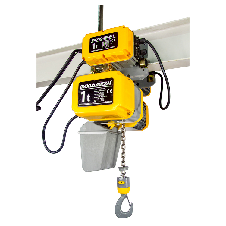
Electrical Control and System Integration
Modern cranes commonly use variable frequency drives (VFD). The hoist’s hoisting and traveling motors can also be frequency‑controlled to achieve smooth start/stop and reduce load swing. When the crane uses vector VFDs with gentle acceleration/deceleration, if the hoist travel remains two‑speed or single‑speed, the hook tends to swing significantly during crane acceleration, affecting positioning and collision avoidance. It is recommended to also use VFDs for hoist travel and coordinate the acceleration/deceleration curves of crane travel, hoist travel, and hoisting through a single controller. In hazardous environments such as metallurgy and foundries, the wire rope hoist must be equipped with dual brakes and an overspeed protection device, connected to the crane’s emergency stop and safety monitoring system.
Power supply integration is also critical. For cranes powered by sliding contact lines, the hoist normally draws power via a small trolley wire or festoon cable. When the hoist travels frequently, the bending radius and tensile strength of the festoon cable must accommodate the motion cycle – otherwise, core breakage will lead to recurring faults. When both remote radio control and pendant control are used, the control logic must give the “stop” command the highest priority. The crane’s main power supply emergency stop must be able to cut the hoist’s main circuit. Upper and lower limit switches should be dual‑redundant to prevent overwinding from a single limit failure.
Installation, Commissioning, and Inspection Points
After the hoist is suspended onto the crane, first check the side clearance between the traveling trolley wheel flanges and the rail to ensure synchronous movement on both sides. Adjust the horizontal and vertical skew of the wheels within the rail tolerances by adjusting eccentric shafts or shims. The wire rope must be wound according to the drum groove direction. For multi‑layer winding, ensure even rope layering and apply appropriate pre‑tension to avoid crushing deformation due to looseness. The torque of wedge sockets or clamp bolts must be tightened strictly according to specifications.
During load testing, apply 1.0, 1.25 (dynamic), and 1.5 (static) of the rated load in sequence, measuring main girder deflection and brake stopping distance. Generally, the static load stopping distance of a wire rope hoist should not exceed 1% of the hoisting speed. If it exceeds this limit, the brake spring must be adjusted or the brake friction lining replaced. Also, verify the upper/lower limit switches and, for dual‑hoist tandem lifts, the height difference between the two hooks; fine‑tune synchronization via VFD parameters if necessary.
Typical Applications and Maintenance
In machine shops for handling molds and workpieces where micro‑positioning accuracy is critical, two‑speed or VFD wire rope hoists are often selected. In corrosive environments such as waste‑to‑energy plants and chemical plants, the wire rope and electrical enclosure require heavy anti‑corrosion treatment, and galvanized or high‑grade stainless steel wire rope should be used. In outdoor yards, the hoist’s wind‑resistant tie‑down system must be coordinated with the crane’s rail clamps – they must not act independently. In daily maintenance, wire rope breakage and wear, brake clearance, and motor current balance of the traveling motion should all be included in the overall crane periodic inspection, rather than treating the hoist as a separate accessory.
Overall View
The wire rope hoist and the overhead crane are not simply a master‑accessory relationship, but rather a coordinated motion and load‑bearing system. If the duty class consistency, electrical interface standardization, and mechanical dimensional compatibility are fully evaluated at the early matching stage, the probability of later frequent failures and forced modifications will decrease significantly. Simply taking a standard hoist and hanging it onto a crane – once put into busy, variable actual operation – will quickly reveal its shortcomings. Only by basing design on process requirements and treating the hoisting mechanism and the bridge motion as an integrated system can long‑term stable and safe operation of the crane system be guaranteed.
 0086 156 1824 5535
 0086 156 1824 5535