Combination of Electric Hoist and Jib Crane
The structure of the jib crane determines how the hoist "moves"
Jib cranes mainly come in three types: pillar-mounted (fixed-column), wall-mounted (travelling), and portable (mobile). Each type has different implications for hoist travel and power supply.
Pillar-mounted jib cranes are the most common. A vertical column is fixed to a foundation, and the jib arm can be rotated manually or electrically, typically between 180° and 360°. The arm is usually made of an I-beam, and the hoist trolley runs along the lower flange of the I-beam, moving radially along the arm's length. In this configuration, the hoist operates in a polar coordinate system: it rotates with the jib while moving radially. For power supply, if 360° continuous rotation is allowed, a slip ring assembly must be installed at the top of the column to prevent cable twisting. If rotation is limited to 180°, a cable drag chain or a spring-driven cable reel can be used, but end stops must be provided.
A wall supports wall-mounted travelling jib cranes; the upper rail is fixed, and the lower rail can be on the floor or on a lower part of the wall. The entire jib can travel along the wall, while the hoist moves transversely along the jib arm. This configuration covers a rectangular area and is ideal for assembly lines with multiple workstations. Power is typically supplied via conductor bars or a towline system that feeds power along the crane's travel direction and then to the hoist. Note that the hoist's travel distance is long, so sufficient cable slack must be allowed to prevent snagging.
Portable jib cranes have a base, often with counterweights and casters, and can be moved to different workstations. They are flexible but have a limited lifting capacity, typically under 500 kg. They are usually equipped with electric chain hoists and often controlled by a wired pendant. Since there is no fixed power point, they are typically fitted with industrial plugs for easy connection/disconnection. Cable management must be convenient to prevent cables from dragging on the floor, which creates tripping or crushing hazards.
Hoist selection: more than just lifting capacity
Many users focus only on lifting capacity and then pair the crane with any hoist, leading to problems. For jib crane applications, hoist selection should consider four key parameters: headroom (hook clearance), travel type, speed control, and ingress protection (IP) rating.
Headroom is critical. The space where a jib crane is installed often has limited overhead clearance. The distance from the hoist hook to the bottom of the I-beam rail determines the actual lifting height you can achieve. For the same 1-ton capacity, a European-style low-headroom electric chain hoist can achieve a headroom of just over 200 mm, whereas a traditional wire rope hoist may require more than 500 mm. If your building has low eaves, choosing the wrong hoist can prevent you from lifting workpieces properly, or the hook may not reach the desired height at its top position. You must calculate the required hoist headroom based on the clearance under the jib, the required lifting height, and the rigging height.
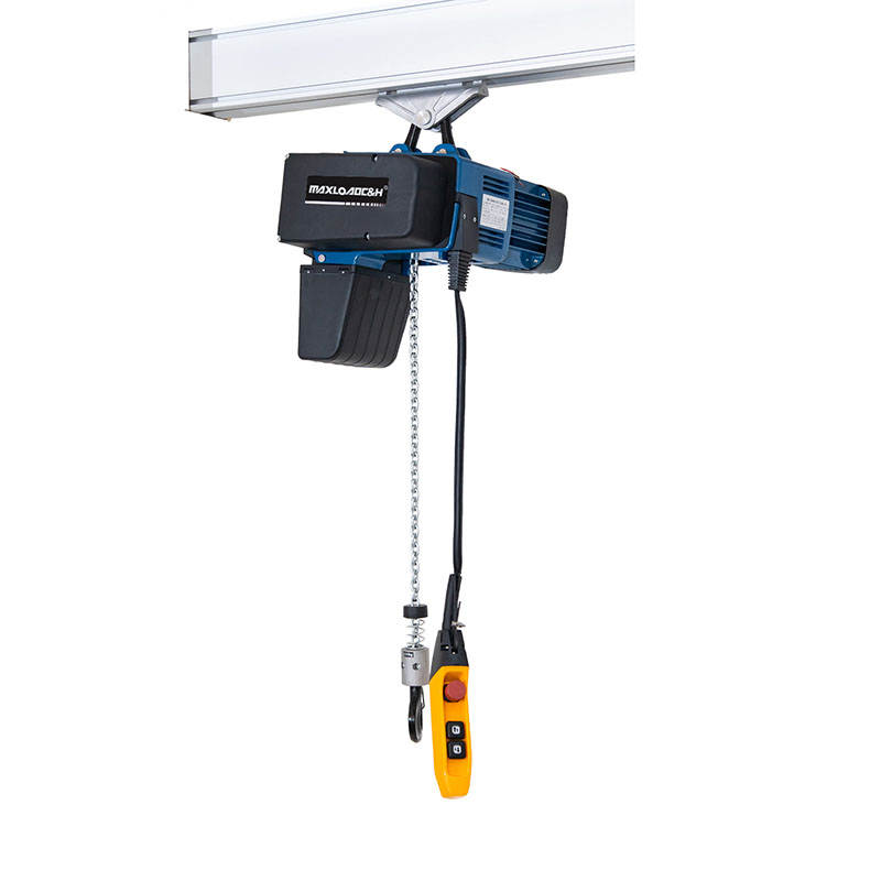
Travel method: On jib cranes, the hoist can move in two ways: manual trolley (hand-geared) or motorised trolley. Manual trolleys are used for infrequent, light-duty applications, where an operator pulls a chain to move the trolley along the I-beam. Motorised trolleys use an electric motor. Note that the jib arm deflects under load, so the I-beam rail is not perfectly horizontal. With a motorised trolley that has a brake, heavy loads may roll on a slope. It is advisable to choose a hoist travel motor with electromagnetic or cone braking that stops immediately when power is cut. If precise positioning is required, two-speed or variable frequency drive (VFD) travel should be used, with a fast/slow speed ratio typically 4:1 or 6:1 for low-speed positioning.
Speed control significantly affects load swing. When a jib crane rotation stops suddenly, or the hoist moves transversely, inertia makes the load swing. Solutions include VFD control for hoist travel, adding a VFD gear motor for jib rotation, and implementing smooth start/stop in the control system. For fragile items or precision assembly, an anti-sway system can be added, or the operator can rely on inching control and skill. Note that if anti-sway is needed, it should be specified at the time of purchase; retrofitting is costly and less effective.
Ingress protection is often overlooked. If the jib crane is installed in a grinding, sandblasting, outdoor, or humid environment, the hoist must have appropriate protection. For general indoor clean environments, IP55 is sufficient. For dusty or steamy conditions, IP65 should be used. For corrosive environments like pickling shops, corrosion protection is required, and wire ropes or chains should be made of stainless steel or coated. Do not use ordinary chain hoists in a foundry; dust will quickly wear them out.
Devil in the details: what makes a good installation
Smooth hoist travel on the I-beam rail depends largely on rail flatness and joint treatment. During manufacture, if welded joints of the I-beam are not ground smooth or if the lower flange has wavy deformation, the hoist wheels will snag, bounce, or even lock. During installation, use a level and a straightedge to check the flatness of the lower flange. Height differences at joints should be kept within 0.5 mm. Both ends of the rail must have sturdy mechanical stops to prevent the hoist from running off the jib arm.
Power supply for jib rotation is a common trouble spot. If slip rings are used, they must be of good quality and the carbon brush dust should be cleaned regularly. If a drag chain system is used, select a cable with high flex life (e.g., continuous-flex cable) and provide adequate bending radius. Never use ordinary cable that twists in the air; the conductors will break quickly. Some sites use spiral cable, but the ends must be fixed securely and strain relief provided; otherwise, breakage at the connector is inevitable.
Duty cycle and classification must match. Many people look only at the nameplate capacity and ignore the classification. For the same 1-ton hoist, an M3 (1 Am) class is suitable for occasional full-load use, with most of the time light loads. For frequent loading/unloading, hundreds of lifts per day, M4 or M5 is required, with upgraded motors, brakes, gears, etc. The jib crane itself has a classification. The classifications of the hoist and crane should match, or the hoist should be one class higher. Otherwise, the hoist may burn out motors frequently before the crane shows wear.
Control system configuration now often uses a wireless remote control with a wired backup. A wireless remote allows the operator to stand at a safe distance with a better view, reducing errors. However, if multiple jib cranes work close together, wireless transmitters may interfere; different frequencies or encrypted pairing should be used. Additionally, an emergency stop button must be prominently located and functionally independent, cutting power to all hoist and jib motions when pressed.
Case studies illustrating the matching logic
Example 1: A precision component machining workshop needed to load/unload two machining centres. Parts weighed about 350 kg, with limited headroom due to spindle interference. A pillar-mounted jib crane was chosen, with a 4-meter arm, 180° rotation, installed between the two machines. A low-headroom electric chain hoist with only 220 mm headroom was selected, with two speeds (8/2 m/min) and wireless remote control. To prevent rotation from hitting the machines, rubber buffers and limit switches were installed at both ends of the rotation range, and the rotation motor speed was reduced using a VFD. After installation, the hook's lowest point still had 150 mm clearance to the floor, the lifting height was sufficient, and slow-speed positioning allowed a single operator to easily change workpieces. This case illustrates how to back-calculate the hoist model based on headroom and match travel speeds and limit devices.
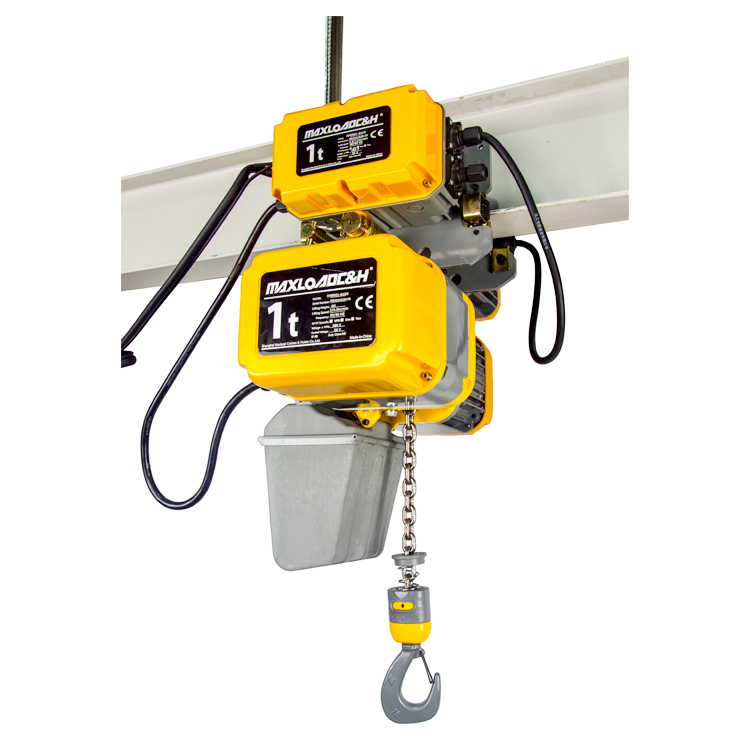
Example 2: An assembly line had four workstations needing one shared lifting device, spanning about 8 meters. A wall-mounted travelling jib crane was used. The bridge travelled along the wall, and the hoist moved transversely to reach different stations. Both bridge and hoist travel were VFD-controlled. The hoist was a 500 kg electric chain hoist with a "float mode" (torque limiting that allows manual movement of the load with ease), enabling operators to guide the workpiece for precise alignment. Key matching points here were the horizontal alignment of the bridge rail, the stiffness of the jib arm, and the calibration of the hoist's float control system. The installation performed well after six months.
Installation and daily inspections are not optional
Foundation requirements for a pillar-mounted jib crane are comparable to those for a small building. Typically, a concrete foundation with anchor bolts is required, and the horizontal level must be within 1/1000. If the foundation settles, the column tilts, causing difficult rotation, increased jib deflection, and the hoist climbing or rolling on slopes. After installation, load tests must be performed: 1.25 times rated load dynamic test with all motions cycled; 1.5 times rated load static test, with jib end deflection less than 1/200 of arm length and no permanent deformation. After testing, recheck all fasteners and welds.
Routine maintenance should focus on lubrication of the hoist chain or wire rope, cleaning of the I-beam lower flange, and wear on slip rings and drag chains. Chain pitch elongation exceeding 3% requires replacement; do not continue using it. The slewing bearing of the jib should be greased periodically; any abnormal noise or increased play should be investigated promptly.
Conclusion
In summary, matching an electric hoist with a jib crane is not simply buying and assembling components; it is a small-scale, customised material handling solution. Only by considering the foundation, structure, hoist parameters, power supply, and control as a whole can you achieve a user-friendly, low-failure-rate device. When reviewing a supplier's proposal next time, use these points to ask questions. A designer who can answer clearly and provide data support is truly knowledgeable.
 0086 156 1824 5535
 0086 156 1824 5535