Workspace Environment Determines KBK System Selection
When configuring a KBK light crane system for a workshop, the first question many people ask is usually, "What capacity (tonnage) do we need?" In practice, however, an even more fundamental question must be answered first: What will support this system? — Will it be suspended from the factory roof structure, or will it stand on its own floor‑mounted columns? Getting this decision right makes all subsequent configuration choices straightforward. Getting it wrong can lead to budget overruns at best and safety hazards at worst.
Suspension Type: The Most Common Choice, but with Strict Prerequisites
In a suspended system, the KBK rails are fixed beneath the factory roof steel structure via suspension clamps and fittings. The self‑weight of the rails, the hoist weight, and the full‑load material weight are all transmitted to the roof steel beams and purlins. The advantages are obvious: it occupies no floor space, leaving the workshop floor completely clear for forklifts and personnel; installation is fast, requiring no foundation excavation or concrete pouring, with typical lead times from site entry to handover of two to four weeks; and overall cost is the lowest among the various structural options.
However, suspended installation has a hard prerequisite: the factory steel structure must be able to withstand these loads. When conducting a site survey, the first task is not to look at the floor, but to look up at the roof — the purlin cross‑section dimensions, material grade, purlin spacing, and the corrosion condition of the steel beams. Without these data, the design cannot proceed. The number of suspension points must be calculated based on rail section, hoist self‑weight, and full‑load capacity, with a safety factor of no less than 4 for each suspension point. This margin is not excessive — it is necessary to account for instantaneous shock loads caused by load swinging during handling, which can reach peak values 1.5 to 2 times the static load.
A common scenario encountered is a factory building more than ten years old, originally designed as a light‑steel structure without any consideration for crane loads, with undersized purlin sections. In such cases, a suspended system is not entirely impossible, but additional steel beams must be added above the suspension areas to enlarge the load‑bearing surface. The cost for this structural reinforcement must be calculated separately from the building's civil works. An even trickier situation is when the factory is leased, and the property management contract explicitly states: "no drilling, welding, or attachment of additional loads to the building structure." In that case, a suspended system is out of the question.
Freestanding (Self‑Supported) Type: The Only Way Out When the Roof Structure Is Inadequate
A freestanding KBK system uses floor‑mounted columns to support the rail system. The entire equipment load is transmitted through the columns to the base plates and then to the floor foundation; the roof structure bears no load at all. When must a freestanding system be chosen? Three typical scenarios: old factory renovations — buildings over a decade old with corroded steelwork, undersized purlins, and missing original drawings, making it unsafe to suspend anything; leased workshops — where the landlord forbids any modifications to the structure; and workshops with possible future layout changes — because a freestanding system can be fully disassembled and reassembled in a new workshop.
Freestanding systems generally have higher load capacities than suspended ones, thanks to their robust steel support columns. But the trade‑offs are clear: they occupy floor space for the columns, and installation costs are higher. Freestanding systems have specific floor requirements: concrete strength of at least C25, and a bearing capacity of 0.15 to 0.3 MPa depending on lifting capacity and span. For new buildings, the installation positions can be预留 during floor pouring; for existing buildings, chemical anchors or expansion bolts are used for fixing.
Flexible Structure: A Lightweight Handling Option
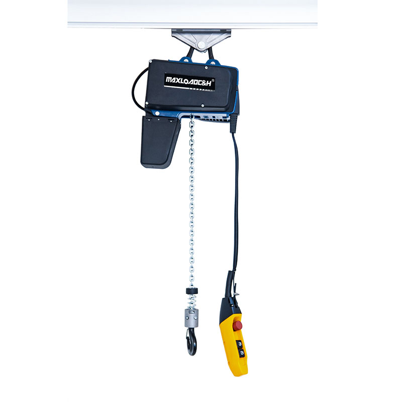
Beyond the support method, there is another important structural dimension: the choice between flexible and rigid rail systems. In a flexible KBK system, the connections between rails and main beams, and between I‑beams and rails, are all flexible. Its support centre spacing depends on the lifting capacity, generally ranging from 30 cm to 3 m; the main beam span for a 1‑tonne load is about 7 m.
The advantage of the flexible structure lies in its lightweight design. The rails are suspended using flexible hangers with wire ropes or chains, imposing a smaller additional load on the roof, making it suitable for light‑duty material handling and workspaces with particularly tight clearances. Its modular design allows flexible layout and rapid combination of rails, enabling 3D light lifting.
However, flexible structures have notable limitations. First is walking asynchrony — the two ends of the main beam tend to move out of sync, with one end leading and the other lagging. Second is a safety difference: the trolleys in a flexible KBK rail system do not have safety devices. If a wheel axle breaks, the trolley could fall completely off the rail. In contrast, rigid‑rail trolleys incorporate side‑plate (wing) designs: even if a wheel is damaged, the side plates still engage the rail and prevent derailment. Additionally, flexible systems require an extra set of steel support structures, and suspended versions need even more steel.
Matching the Electric Hoist
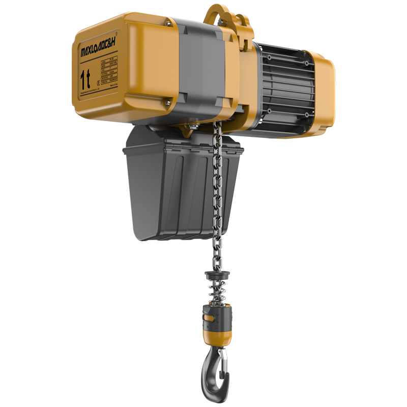
The pairing of a KBK system with an electric hoist is primarily about matching the working rhythm and positioning accuracy of the workstation. Chain electric hoists are currently the most common choice for KBK systems, mainly due to their economy, efficiency, and low‑noise characteristics.
The frequency of use at the workstation determines the hoist's duty class. A maintenance station used only occasionally can suffice with class A1; a production line running 6 to 8 hours daily requires at least class A3. For applications requiring precise alignment — for example, inserting a locating pin on a mould into a machine's mating hole — a two‑speed hoist is essential. Single‑speed hoists typically offer only one lifting speed, around 8 m/min, which is fine for general handling but makes accurate positioning difficult. Two‑speed hoists can reduce the slow speed to 1‑2 m/min and with frequency inverter control, achieve millimetre‑level inching.
For workshops with limited headroom, a low‑headroom chain electric hoist paired with KBK rails reduces the distance between the equipment and the roof beams, increasing the effective lifting height by up to 500 mm. For multi‑station cross‑area transfer, a KBK crane combined with a travelling electric hoist enables flexible movement of materials along the rails.
The Underlying Logic of Selection: Starting from the Workspace Environment
Ultimately, KBK selection is not a purely technical choice but a matching exercise with the workshop conditions. If the workshop roof is robust and has spare structural capacity, choose a suspended system — lower cost, faster installation, and a completely clear floor. If the roof is inadequate or cannot be modified, choose a freestanding system — a slightly higher budget buys safety and flexibility. If loads are light, positioning accuracy requirements are low, and budget is tight, flexible rails can meet the need. For heavy loads, precise positioning, and high usage frequency, rigid rails are the more reliable choice.
In actual selection, three core parameters — lifting capacity, span, and headroom — must be matched comprehensively. Lifting capacity should be selected as "maximum load × 1.25 safety factor". The span should be determined by the workstation width plus a safety margin of 300 to 500 mm on each side. Headroom should ensure a minimum clearance of 200 mm between the lowest point of the lifting device and any obstacle below.
Different workstation scenarios have different priorities. In machining workshops with fluctuating loads and a need for precise alignment, rigid rails with two‑speed hoists are a sound configuration. In assembly line areas with high‑frequency, continuous operation, rigid rails with electric travel are more suitable. For clean rooms or environments requiring corrosion resistance, aluminium rails are a better choice.
The essence of selection is translating the constraints of the workspace environment into technical parameters. Can the roof support it? Can the floor bear it? How heavy is the load? How frequently is it moved? How precise does positioning need to be? Once these questions are answered, the solution naturally follows.
 0086 156 1824 5535
 0086 156 1824 5535