Selecting KBK Cranes Based on the Workstation Environment
The most common mistake in selecting workstation lifting equipment is making a decision based solely on the load capacity. A KBK system is essentially a material handling network embedded in the workshop production process. Its value lies not in how heavy it can lift, but in whether it can deliver the right material to the right place at the right time. The first step in selection is not to browse product catalogues, but to understand the workstation.
Understand the workstation's "cards"
Before discussing any structural type, three questions must be answered: What is being lifted? Where is it being lifted? Who supports it?
Load characteristics are the most obvious hard indicators. KBK systems typically have load capacities ranging from 0.125 tons to 2 tons. Heavier loads require higher rail rigidity, larger support spacing, and more capable hoist lifting mechanisms. However, what many overlook is the "nature" of the load – is it a high-frequency repetitive handling task of 200 lifts per day, or occasional maintenance lifting? Are the loads regular metal parts or irregularly shaped components? The former determines the working class; the latter determines the type of lifting attachment. An inadequate working class leads to premature fatigue failure; the wrong attachment causes the workpiece to swing dangerously in the air.
Space conditions determine how and how far the rails can run. In workshops with a clear height of less than 4 metres, a standard suspended KBK may not even provide enough lifting travel for the hoist. In old workshops with densely packed columns, the rails must curve around them and incorporate switches, significantly increasing complexity. In old workshops where the floor is cluttered with equipment, there may be no place to position free-standing posts. Before selection, spread out the workshop floor plan and mark every column, every aisle, every ventilation duct, and every cable tray – these are the real factors that decide whether a solution can be implemented.
The building structure is the core variable that determines whether to choose a suspended or a free‑standing system. This issue is most frequently overlooked during selection, and the consequences are most severe – discovering mid‑installation that the roof cannot support the system costs far more in rework than spending an extra two days on preliminary measurement.
Three mainstream structural types, each in its place
KBK systems can be divided into three mainstream structural forms based on support method and rail rigidity. Understanding their essential differences is more important than memorising specifications.
Free‑standing system: independent of the building, stands on its own
The core logic of a free‑standing KBK is "self‑support" – it uses floor‑mounted posts and top connecting beams to form an independent support frame. All loads from the rail system are transmitted through the posts to the foundation, with no load imposed on the building structure. This means it can be installed in any workshop with a hardened floor, without being constrained by roof load‑bearing capacity.
When is it indispensable? In the renovation of old workshops, where the steel structure is corroded, original drawings are lost, and no one dares to hang anything from the roof. In rented workshops – where the owner does not permit drilling or welding on the structure. In workshops where production lines may be relocated, the free‑standing system can be dismantled as a whole and reassembled elsewhere. The price of a free‑standing system is higher – additional posts, base beams, and foundation work make the initial investment higher than a suspended system. But if the risks of "cannot install" and "dare not install" are factored in, this extra cost is not necessarily wasted.
Free‑standing systems have inherent advantages in span. Rigid free‑standing systems can have support centre spacings of 6 to 9 metres, with main beam spans up to 9 metres and main beam lengths up to 10 metres. For workstations that need to cover a relatively large rectangular area, this is a parameter that cannot be ignored.
Suspended system: space‑saving, cost‑effective, but with prerequisites
The suspended system is the most common choice in workstation applications, accounting for about 70% of shipments. The rails are fixed by suspension clamps to the steel structure beneath the workshop roof, and all loads are transferred to the building's steel beams and purlins. The advantages are straightforward: no floor space occupied, so forklifts and personnel can pass freely; short installation time, with no need for foundation excavation or concrete pouring; and overall lower cost than a free‑standing system.
But the suspended system has a hard prerequisite – the workshop steel structure must be able to withstand these loads. During selection, it is not enough to check the cross‑sectional dimensions of the purlins; one must also verify the steel grade, purlin spacing, and corrosion condition of the steel beams. The layout of suspension points requires load calculations, and the safety factor for each suspension point must be no less than 4 – for a working load of 500 kg, the breaking load of the clamps and connecting components must exceed 2000 kg. This margin is not for show; it is to handle the instantaneous impact caused by load swinging during lifting, where peak impact loads can reach 1.5 to 2 times the static load.
Rigid suspended systems have support centre spacings ranging from 1.6 m to 9 m, offering wide span adaptability. Flexible suspended systems have suspension point spacings related to the lifting capacity, generally between 30 cm and 3 m.
Flexible system: modular and reconfigurable
"Flexible" here refers to the adjustability of the rail connection method and structure, not to material softness. Flexible KBK uses flexible connections between rails and main beams. The support centre spacing is related to the lifting capacity – for a 1‑ton load, the main beam span can reach 7 m and the main beam length 8 m; for a 2‑ton load, twin beams and electric travel are required.
The most prominent value of a flexible system lies in its reconfigurability. It adopts a modular, combinational design – rails, main beams, and travel mechanisms are all standard modules that can be extended, shortened, or reassembled according to changes in production needs. When workshop layouts are adjusted, the flexible KBK can adapt to new stations and workflows at minimal cost. One case shows that moving a twin‑beam station by 4 metres took only 90 minutes. For industries with fast product iteration and frequent production line changes, the long‑term value of this flexibility often exceeds the price difference of the equipment itself.
The trade‑offs of a flexible system are positioning accuracy and travel synchronisation. The left and right sides of the main beam do not move in perfect synchrony, making precise positioning more difficult than with a rigid system. In addition, safety in extreme conditions deserves attention – if the wheel axle of a flexible trolley breaks, the trolley may fall out of the rail; rigid systems, by contrast, have side‑plate designs on the trolley that keep it captured in the rail even if a wheel is damaged.
Rigid or flexible? Not a binary choice
Rigid and flexible systems are not opposing poles, but two design philosophies suited to different working conditions.
Rigid systems use rigid connections between I‑beams and profile rails, and between profile rails and main beams. Their advantages are precise positioning, synchronous travel, and lower headroom – the flush‑mounted hanger design allows a hoist lifting height increase of more than 1000 mm compared to a flexible system under the same steel structure elevation. Support centre spacings are larger – 6 to 9 metres between posts means fewer posts cover a larger area.
Flexible systems use flexible connections between components. Their advantages are modularity and adjustability. However, flexible systems require greater headroom and offer relatively less lifting height; the main beam does not travel synchronously left‑to‑right, making precise positioning difficult.
To choose rigid or flexible, ask whether the core demand of the workstation is "precision" or "changeability". For precision assembly, die changing, and applications requiring accurate positioning, the rigid system has the edge. For frequent production line adjustments, high‑mix low‑volume production, and situations needing rapid response to layout changes, the flexibility of the flexible system offers greater value.
Matching the electric hoist
The electric hoist is the execution terminal of the KBK system, and its selection logic follows the same principles as the rail system.
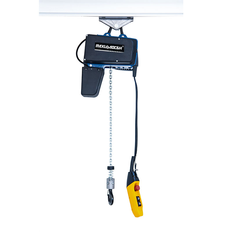
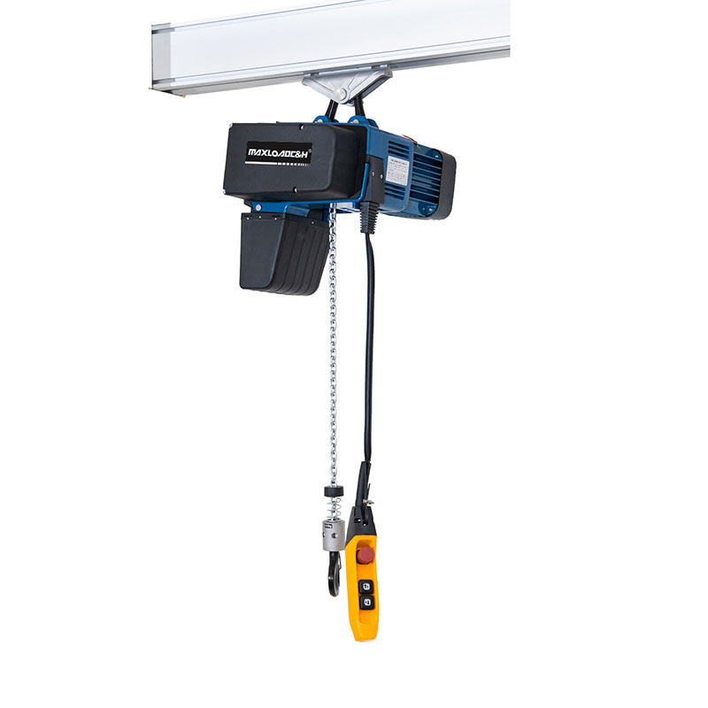
Type selection: Chain electric hoists are the most common match for KBK systems – cost‑effective, low noise, easy maintenance, and suitable for light industry and general manufacturing. Wire rope electric hoists are more compact, offer greater lifting heights, and are better for heavy‑duty applications.
Environmental adaptation: Standard types are used in ordinary workshops; sealed housings are required in dusty environments to prevent debris from affecting operation; corrosion‑resistant types are needed in damp or corrosive environments; explosion‑proof types must be used in areas with explosion protection requirements.
Control method: For small capacities and short spans, manual control may be sufficient; conventional scenarios use pendant control; where operators cannot approach the load – such as high‑temperature, toxic, or high‑risk areas – wireless remote control is essential.
Working class: High‑frequency operation requires a higher working class – selection cannot be based on capacity alone. Two hundred lifts per day versus two lifts per week place completely different demands on the motor, gearbox, and brake of the hoist.
Selection should not focus only on equipment specifications; it must consider the workstation's motion cycle – where the material comes from, where it is lifted to, how many times per day, the weight of each piece, and whether rotation or lateral movement is needed. Drawing a flow chart of the workstation's handling motions is far more useful than flipping through ten product catalogues.
 0086 156 1824 5535
 0086 156 1824 5535